
Technical Services logo with red banner and blue swoosh accents
249 VAN Launch Kit 249 VAN Consumer Brochure Smart Thermostat Sell Sheet 249 VAN Launch Kit

Unlock the Full Potential

View Quick Start Guide

This installation was on a 4-story home, and the tech had not yet gone to the basement to troubleshoot the “infinity” water source heat pump, as he was told he by the homeowner. He was in the attic at the infinity furnace above the 4th floor. He was getting his dcv in the proper range on his A and B green plug on the air handler, 3 to 4 vdc. His indoor board ohm reading was in range, 28k to 32 k. The tech ohmed out the A and B thermostat wires on the water source heat pump from the upstairs. His ohm reading was not in range of a normal infinity board. His reading was around 64.4k. The tech then made the long walk to the basement where the “geothermal heat pump” was located. Bingo. 

Now get out there and organize some zone wiring!

Zone equipment would be identified as indoor unit- blue black/ outdoor unit-blue green:
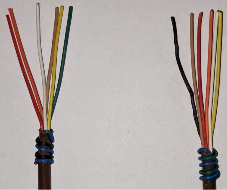
Two multicolored wire bundles with exposed ends and wrapped bases on a white background
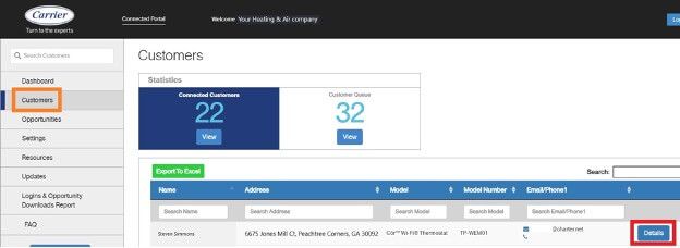
Dashboard showing customer stats, a left navigation menu, and a blue data table with a highlighted action button.

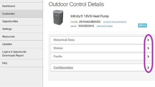
I have cropped some screens, and modified the serial numbers to keep certain dealer and customer’s information private. Setting the customers up on the portal is an easy process and could reap many benefits. Carrier and Bryant are going to begin utilizing this portal more with new upcoming equipment.


Get out there and get connected to the portal!
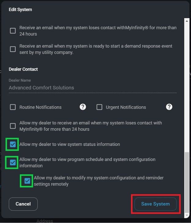
Dark-themed settings dialog with checkboxes and Save System button highlighted in red.
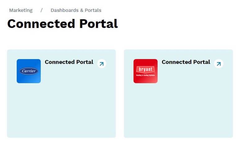
Marketing dashboard titled “Connected Portal” with two pale blue portal cards, one blue and one red icon.
Web dashboard showing outdoor control details with accordion panels and right-side expand arrows.

*Wiring diagrams highlighted with colors chosen for high contrast- not for wire color designation*

Low voltage starts in the red box at the transformer, 24vac goes to the Indoor Fan Board (IFB), through a fuse and on to the thermostat. Depending on what the thermostat calls for, 24vac will be sent down a different wire(s) to turn on/off the multiple devices in the system. The other low voltage wire (C) has an unbroken path to EVERY component in the unit. I have highlighted the pathway in blue and circled each component in purple. This wire/path is something each device has in “common”—it is the common wire. In layman’s terms, the common wire is the return pathway for voltage to come back to the transformer since it left out on the 24vac side.


The Common wire/terminal is always the one thing that is relatable or in common with the surrounding wires/terminals. Relays, motors, control boards, and even transformers all have some type of common wire/terminal. Common for a relay isn’t the same as common on a motor, but within each given device they carry the same meaning. Now go back and reread the second paragraph above—it will have a deeper meaning now.


Challenge: Check out the high voltage side of the Transformer. It has a COM terminal…. it’s not low voltage common. What is it?


That’s all.

Loading PDF…

Picture of Steven Simmons

Roger Siling

Technical Services Trainer

August 5, 2020

What Is a Thermistor & How Does It Work?

Modern HVAC systems today rely on thermistors for proper sensing of air and liquid temperatures to be used by system control boards for adjustments to operational speeds. As temperature conditions change, the thermistor reports these temperatures to the control boards which then adjust the compressor and blower speeds to compensate for these changing conditions.


  • Thermistor type selection varies according to the use needed or application required.
  • HVAC thermistors resistance ranges used by CBP are the 10k-ohm & 50k-ohm varieties.
  • These are called NTC Thermistors, as they respond inversely to the temperature chance.
  • If the measured temperature rises, then the thermistor resistance value drops.
  • Likewise, if the measured temperature drops, then the thermistor resistance value rises.
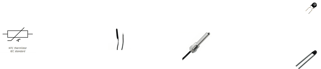
White background with small black product icons and a tiny logo across the top.

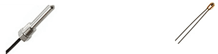
Glass Encapsulated NTC Thermistors


These are NTC temperature sensors sealed in an airtight glass bubble. They are designed for use with temperatures above 150°C, or for printed circuit board mounting, where ruggedness is a must. Encapsulating a thermistor in glass improves the stability of the sensor as well as protecting the sensor from the environment. They are made by hermetically sealing bead type NTC resistors into a glass container. The typical sizes range from 0.4 – 10mm in diameter.

Two small metal probe sensors with wires, one silver and one gold-tipped, on a white background

NTC Thermistors

An NTC thermistor is a thermally sensitive resistor whose resistance exhibits a large, precise and predictable decrease in resistance, as the core temperature of the element increases over the operating temperature range.

Characteristics of NTC Thermistors

Unlike RTDs (Resistance Temperature Detectors), which are made from metals, NTC thermistors are generally made of ceramics or polymers. Difference materials used result in different temperature responses, as well as other characteristics.

Temperature Response

While most NTC thermistors are typically suitable for use within a temperature range between -55°C (-67°F) and 200°C (392°F), where they give their most precise readings, there are special families of NTC thermistors that can be used at temperatures approaching absolute zero (-273.15°C (-459.67°F) as well as those specifically designed for use above 150° C (302°F).

Thermistors are of two types, NTC (negative temperature coefficient) and PTC (positive temperature coefficient types). As their name indicates, the resistance of an NTC thermistor will decrease with temperature rise and the resistance of a PTC thermistor will increase with temperature rise.


Both PTC as well as NTC thermistors can be checked by using an analogue or digital multimeter. Keep the analogue or digital multimeter in resistance mode. Connect the multimeter leads to the thermistor leads. Polarity is not an issue here. Now heat the thermistor by exposing to a known temperature source. You can see the multimeter reading smoothly increases or decreases depending on whether the thermistor under test is PTC or NTC. This will happen only for a healthy thermistor.


For a faulty thermistor, following observations are possible: The change in reading will not be smooth or there will not be any change. A shorted thermistor will always read zero while an open thermistor will always read infinity.

Using an ohmmeter to test the thermocouple will determine if the thermocouple sensor is defective or not.


If a thermistor goes out of calibration, shorts, or is open, then the HVAC system cannot adjust operational speed according to the changing load condition. A simple test meter can be used for testing of the thermistor.


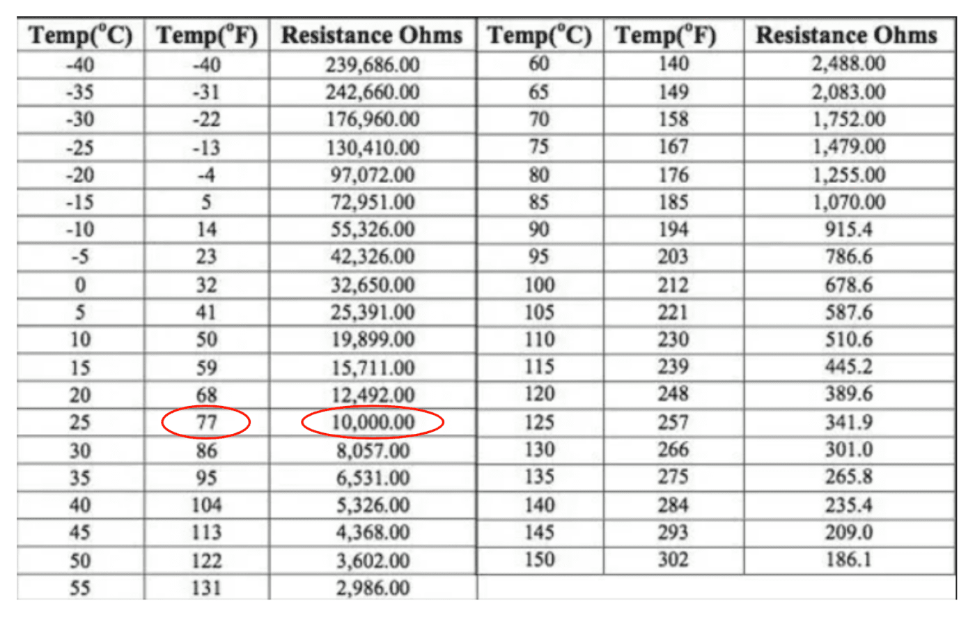
Using the following 10K-ohms chart, and based on the thermistors associated location temperature, then ohm out the thermistor quickly and compare the ohms value from the chart to the actual ohms reading on the meter.

Table of temperature and resistance values; one row is circled in red around 25°C and 77°F.

That is all there is to testing the thermistor, reading should be with-in 5-10 percent depending on the thermistors tolerance value.

249 VAN Launch Kit 249 VAN Consumer Brochure Smart Thermostat Sell Sheet 249 VAN Launch Kit

Unlock the Full Potential

View Quick Start Guide

This installation was on a 4-story home, and the tech had not yet gone to the basement to troubleshoot the “infinity” water source heat pump, as he was told he by the homeowner. He was in the attic at the infinity furnace above the 4th floor. He was getting his dcv in the proper range on his A and B green plug on the air handler, 3 to 4 vdc. His indoor board ohm reading was in range, 28k to 32 k. The tech ohmed out the A and B thermostat wires on the water source heat pump from the upstairs. His ohm reading was not in range of a normal infinity board. His reading was around 64.4k. The tech then made the long walk to the basement where the “geothermal heat pump” was located. Bingo. 


More to Explore

Family relaxing in a bright living room, parents on a gray couch with laptops while children play nearby
By Austin Sims August 4, 2026
At Mingledorff's we understand your business. We are your #1 HVAC and plumbing distributor choice. Trust our experience. Contact us today!
Mingledorffs
By Jenny Reed August 4, 2026
At Mingledorff's we understand your business. We are your #1 HVAC and plumbing distributor. Trust our experience. Contact us today!
Bright hobby shop with display cases, counter, and model kits; a few people stand near the back.
By Jenny Reed August 3, 2026
At Mingledorff's we understand your business. We are your #1 HVAC and plumbing distributor. Trust our experience. Contact us today!
Bright hobby shop interior with display cases, model kits, and a counter with two people inside.
By Jenny Reed August 3, 2026
At Mingledorff's we understand your business. We are your #1 HVAC and plumbing distributor. Trust our experience. Contact us today!

Heat Pump

Keep up with the latest HVAC news from Mingledorff’s Inc.