



Technical Services logo with red banner and blue swoosh accents
249 VAN Launch Kit 249 VAN Consumer Brochure Smart Thermostat Sell Sheet 249 VAN Launch Kit

Unlock the Full Potential

View Quick Start Guide

This installation was on a 4-story home, and the tech had not yet gone to the basement to troubleshoot the “infinity” water source heat pump, as he was told he by the homeowner. He was in the attic at the infinity furnace above the 4th floor. He was getting his dcv in the proper range on his A and B green plug on the air handler, 3 to 4 vdc. His indoor board ohm reading was in range, 28k to 32 k. The tech ohmed out the A and B thermostat wires on the water source heat pump from the upstairs. His ohm reading was not in range of a normal infinity board. His reading was around 64.4k. The tech then made the long walk to the basement where the “geothermal heat pump” was located. Bingo. 

Picture of Bubba Moore

Bubba Moore

Technical Services Manager Southeast District

February 10, 2022

Troubleshooting Electrical Problems: Voltage and Current

Troubleshooting electrical problems in an HVAC system can feel complicated. Sometimes the problem is overlooked as a faulty part. How often do we look beyond the obvious after the motors or compressors fail electrically?


Let’s first look at the incoming voltage. If the voltage is too high or too low, it can cause the motor to fail due to overheating. The voltage should fall between a minimum and a maximum limit that is listed on the data plate of the components. The voltage that is going to a motor or compressor should be within plus or minus 10% of the voltage listed on the data plate. For example, a 208/230-volt motor voltage range would be between 187 volts (208 – 10%) and 253 volts (230 +10%). On 3-phase units, voltages between phases must be balanced within 2%, or we have what is called phase imbalance. For example, if there was a 5% imbalance on the three- phase voltage, it could cause the motor winding temperature to increase 50% over a safe level. If the voltages are outside of this plus or minus 10% range, or there is more than 2% phase imbalance on three phase components, then it will have to be determined if the problem is from the electrical panel or the incoming power supplied to the building that will have to be corrected. If it is not corrected, motors and compressors will continue to fail.


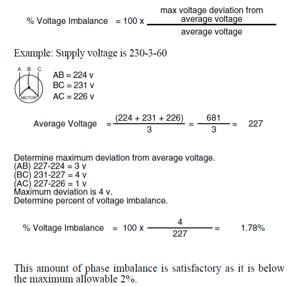
You can use this formula below to determine the percentage of voltage imbalance coming to a unit, or the voltage going to the motor or compressor.

Formula and example for calculating voltage imbalance from three phase supply readings.

As we discuss current imbalance, keep in mind that voltage imbalance will cause current imbalance. However, current imbalance will happen without a voltage imbalance. Current imbalance between any two legs of a three phase system should never be above 10%. What can cause the current imbalance? When there is a current imbalance, look for poor points on a contactor, loose crimp connectors, lugs on disconnects or corrosion. All this can cause high resistance on one leg of power in a three-phase unit. Current, like most things, will follow the path of least resistance. When this happens, the current will increase in the other two legs of power, causing the other two windings in the motor to generate more heat and eventually damaging the motor or compressor.


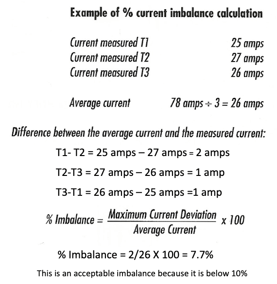
You can use this formula below to determine the percentage of current imbalance on the load side going to the equipment, motor or compressor.

Example showing current imbalance calculation with T1 25A, T2 27A, T3 26A and 7.7% imbalance

Always keep in mind that the voltage to compressor terminals or motor connections during operation must be within voltage range indicated on unit nameplate. On three-phase units, voltages between phases must be balanced within 2%, and the current within 10%. Use the formulas above to determine the percent of voltage or current imbalance if there have been motor or compressor failures in a unit.


The voltage imbalance formula is in most three-phase installation instructions.


Sources:

48HC07-12 Installation Instructions

48TJ004-014 Product Data

HVAC SERVICING PROCEDURES

249 VAN Launch Kit 249 VAN Consumer Brochure Smart Thermostat Sell Sheet 249 VAN Launch Kit

Unlock the Full Potential

View Quick Start Guide

This installation was on a 4-story home, and the tech had not yet gone to the basement to troubleshoot the “infinity” water source heat pump, as he was told he by the homeowner. He was in the attic at the infinity furnace above the 4th floor. He was getting his dcv in the proper range on his A and B green plug on the air handler, 3 to 4 vdc. His indoor board ohm reading was in range, 28k to 32 k. The tech ohmed out the A and B thermostat wires on the water source heat pump from the upstairs. His ohm reading was not in range of a normal infinity board. His reading was around 64.4k. The tech then made the long walk to the basement where the “geothermal heat pump” was located. Bingo. 


More to Explore

Family relaxing in a bright living room, parents on a gray couch with laptops while children play nearby
By Austin Sims August 4, 2026
At Mingledorff's we understand your business. We are your #1 HVAC and plumbing distributor choice. Trust our experience. Contact us today!
Mingledorffs
By Jenny Reed August 4, 2026
At Mingledorff's we understand your business. We are your #1 HVAC and plumbing distributor. Trust our experience. Contact us today!
Bright hobby shop with display cases, counter, and model kits; a few people stand near the back.
By Jenny Reed August 3, 2026
At Mingledorff's we understand your business. We are your #1 HVAC and plumbing distributor. Trust our experience. Contact us today!

Bright hobby shop interior with display cases, model kits, and a counter with two people inside.
By Jenny Reed August 3, 2026
At Mingledorff's we understand your business. We are your #1 HVAC and plumbing distributor. Trust our experience. Contact us today!


Heat Pump

Keep up with the latest HVAC news from Mingledorff’s Inc.