
Technical Services logo with red banner and blue swoosh accents
249 VAN Launch Kit 249 VAN Consumer Brochure Smart Thermostat Sell Sheet 249 VAN Launch Kit

Unlock the Full Potential

View Quick Start Guide

This installation was on a 4-story home, and the tech had not yet gone to the basement to troubleshoot the “infinity” water source heat pump, as he was told he by the homeowner. He was in the attic at the infinity furnace above the 4th floor. He was getting his dcv in the proper range on his A and B green plug on the air handler, 3 to 4 vdc. His indoor board ohm reading was in range, 28k to 32 k. The tech ohmed out the A and B thermostat wires on the water source heat pump from the upstairs. His ohm reading was not in range of a normal infinity board. His reading was around 64.4k. The tech then made the long walk to the basement where the “geothermal heat pump” was located. Bingo. 

Now get out there and organize some zone wiring!

Zone equipment would be identified as indoor unit- blue black/ outdoor unit-blue green:
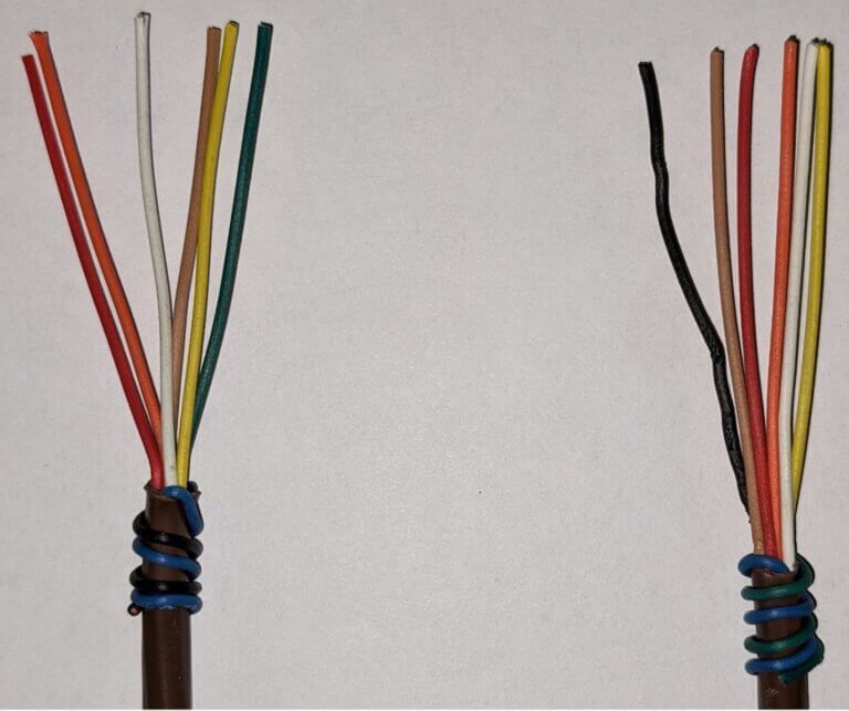
Two exposed wire bundles with colored strands on a white background, one tied with blue tape
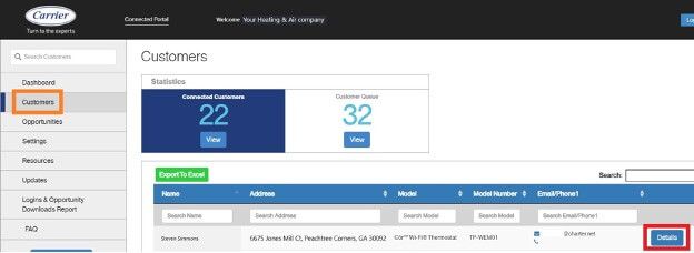
Web admin dashboard on Customers page with left navigation, stats cards, and a customer table with action buttons

I have cropped some screens, and modified the serial numbers to keep certain dealer and customer’s information private. Setting the customers up on the portal is an easy process and could reap many benefits. Carrier and Bryant are going to begin utilizing this portal more with new upcoming equipment.


Get out there and get connected to the portal!
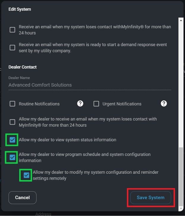
Dark-themed settings dialog with checkboxes and a blue “Save System” button highlighted at bottom right.
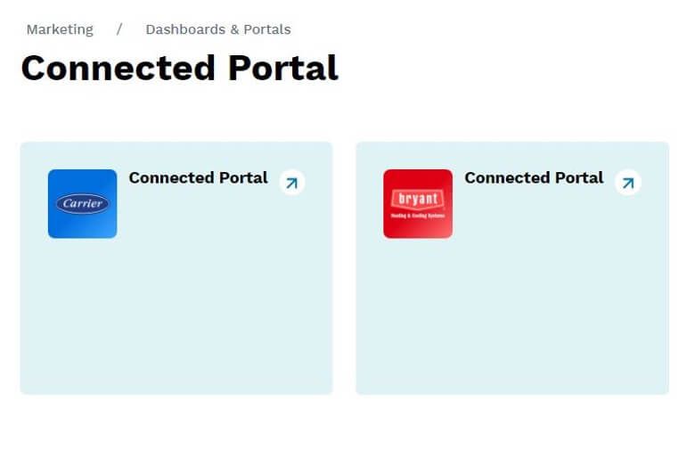
Dashboard page titled “Connected Portal” with two pale blue portal cards, one blue and one red.
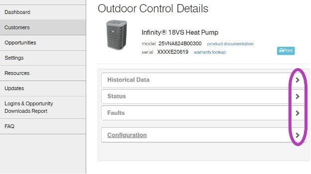
Outdoor Control Details webpage showing a listed device, navigation menu, and section tabs with expand arrows.

*Wiring diagrams highlighted with colors chosen for high contrast- not for wire color designation*

Low voltage starts in the red box at the transformer, 24vac goes to the Indoor Fan Board (IFB), through a fuse and on to the thermostat. Depending on what the thermostat calls for, 24vac will be sent down a different wire(s) to turn on/off the multiple devices in the system. The other low voltage wire (C) has an unbroken path to EVERY component in the unit. I have highlighted the pathway in blue and circled each component in purple. This wire/path is something each device has in “common”—it is the common wire. In layman’s terms, the common wire is the return pathway for voltage to come back to the transformer since it left out on the 24vac side.


The Common wire/terminal is always the one thing that is relatable or in common with the surrounding wires/terminals. Relays, motors, control boards, and even transformers all have some type of common wire/terminal. Common for a relay isn’t the same as common on a motor, but within each given device they carry the same meaning. Now go back and reread the second paragraph above—it will have a deeper meaning now.


Challenge: Check out the high voltage side of the Transformer. It has a COM terminal…. it’s not low voltage common. What is it?


That’s all.

Loading PDF…

Picture of Steven Simmons

Steven Simmons

Technical Services Manager Southwest District

February 10, 2022

All About Heaters

At first glance, a residential strip heat kit could look intimidating. I want to break down the operation and troubleshooting in a way that should give you confidence. Be careful and keep safety in mind while performing the tasks mentioned in this article because the power will have to be on to make these checks. Although different brands will look slightly different, the concept and troubleshooting will be the same.


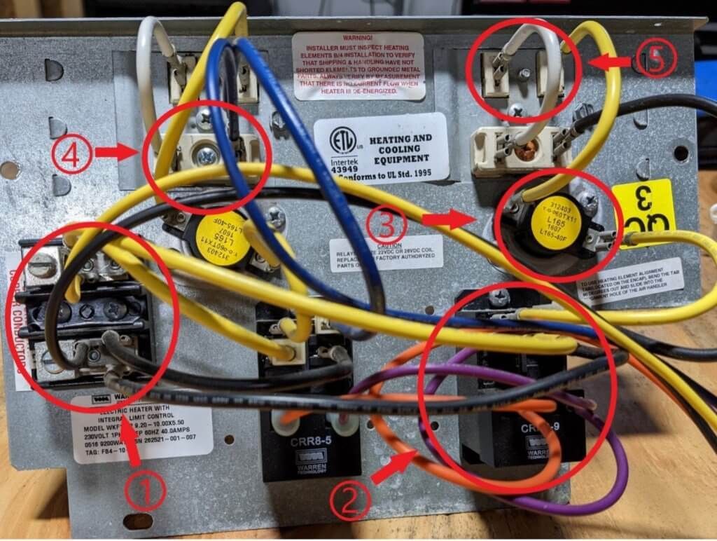
Here are the different parts of a double (10kw) heat kit:

Wiring panel with yellow, red, and black cables, red circled components, and labels on a metal backplate
  1. High voltage terminal block
  2. DC Heater relay with an AC to DC rectifier attached
  3. High temp auto resettable limit
  4. High temp fusible link
  5. Electric heater


Okay, let’s break this heater down even further and discuss each of the 5 different parts in depth for proper operational checks when a heater kit isn’t working:


1. High voltage terminal block:


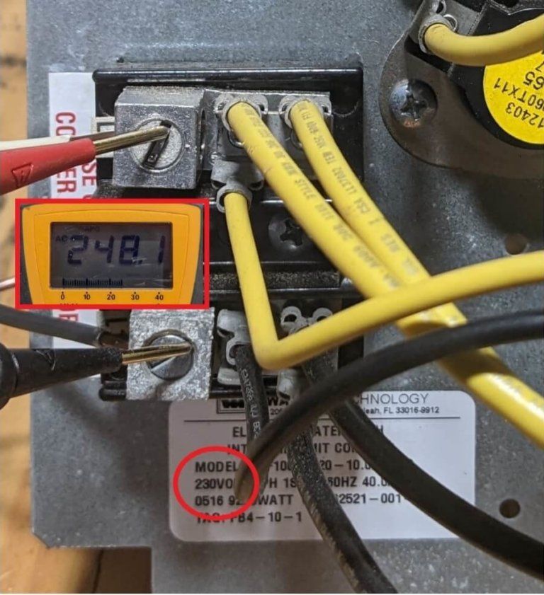
The terminals should read the rating voltage displayed on the heater at all times. In this example the kit is rated for 230v. It is common for heat kits to have a separate power source and this voltage should be confirmed to ensure a breaker wasn’t tripped.

Close-up of electrical panel wiring with a handheld multimeter reading 242.

2. DC Heater relay with an AC to DC rectifier attached:


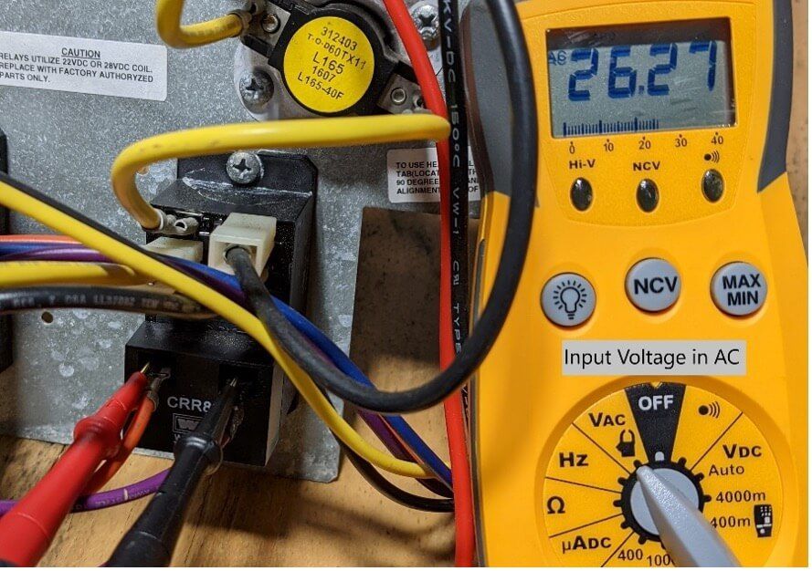
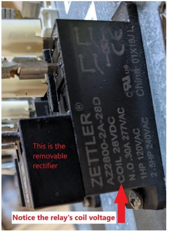
-LOW VOLTAGE-This heater relay consists of two parts, the actual relay and a rectifier. Notice the voltage on this relay is 28vdc. Some relays can be 22vdc.

Digital multimeter reading 26.27 beside yellow wires and an electrical connection panel
Close-up of a black Zettler relay with red annotations pointing to the removable rectifier and coil voltage.
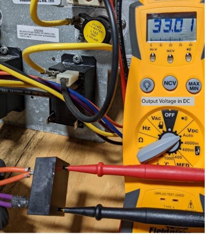
Digital multimeter probing wires in an electrical panel, displaying 331 on a yellow device.

Verify that the rectifier is receiving 24vac. Once this has been proven, the rectifier can be removed to confirm proper output voltage. In this example, the output is reading 33vdc. If the voltage output were to be zero, then it would indicate a faulty rectifier. When the relay receives the correct voltage, the relay should close its contacts.


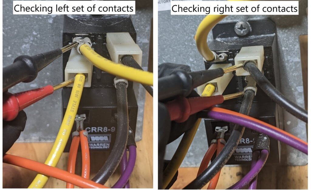
-HIGH VOLTAGE- These relays consist of two set of contacts. One set is located on the top left of the relay and another on the top right. When the relay doesn’t have proper low voltage to energize the coil or if the coil is faulty, the contacts will read 240vac. If the relays close correctly with applied low voltage, then the contacts will show 0vac when checked in this manner:

Checking left and right contact sets on electrical wires and components

3. High temp auto resettable limit:


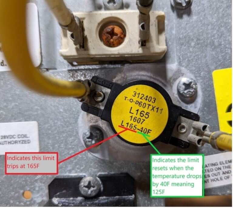
This limit, like many other limits, is displaying its tripping and resetting temperatures. This information can be used when selecting a universal limit or when troubleshooting if the limit is opening/ closing at the right temps. The resettable limit and the fusible link test and function in the same manner EXCEPT that the limit will reset itself and the fusible link cannot. Troubleshooting and operation for this limit will be under #4 fusible links.

Close-up of a thermostat with yellow and green wires and labels marking 165F trip and 125F reset limits

4. High temp fusible link:


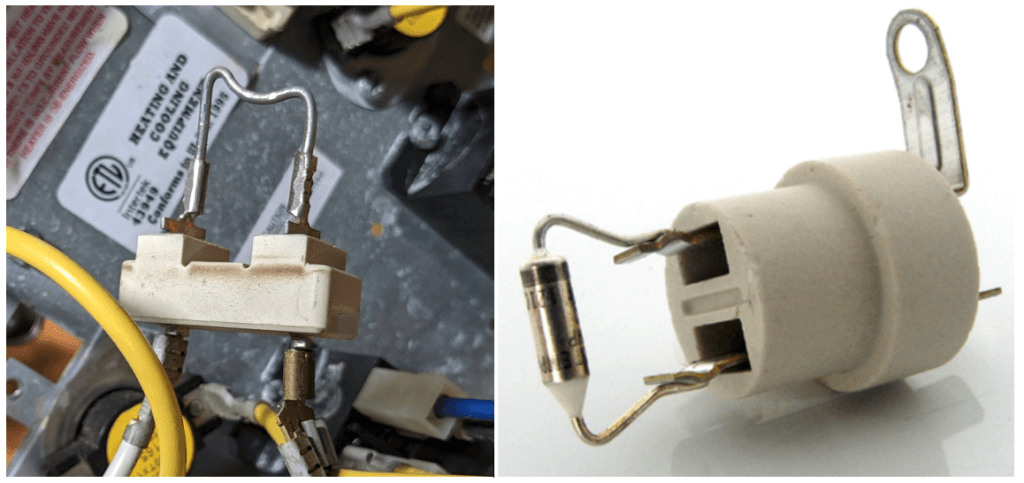
Fusible links are the “backup limit” for when the resettable limit fails or the heater draws too many amps. They typically have a melt/open point of around 300F. Here are the two most common fusible links: The link that is wire only will actually melt and therefore open the power circuit physically and can be seen but, the link that has a device on the wire will internally open and will not alter its look when tripped.

Close-up of a white automotive fuse holder with metal clips beside car wiring harnesses

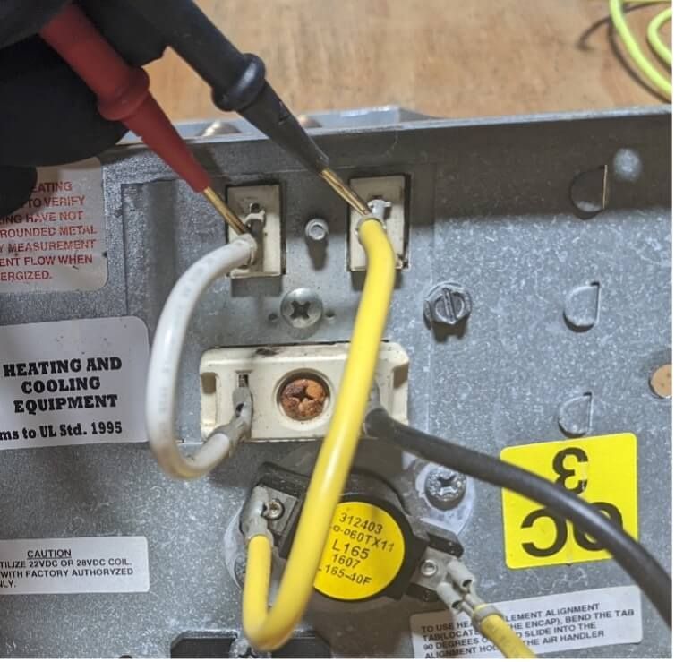
If a limit or fusible link is suspected for a heater not functioning, then simply check the voltage with a meter to ensure that the voltage drop across it is 0vac in the same manner as the contacts were checked on the relay. If a meter were to read 240v, then the limit is open/ or the fusible link has been melted/opened.


5. Electric heater


The electric heater is the star of the show and the easiest to check. This is the meeting place for both 120vac power legs and SHOULD read 240vac. If your meter reflects the heater has 240vac but the current (amps) is zero (assuming the amp clamp is accurate) then this would indicate the heater has failed and is “electrically open” and should be replaced. The meter leads should be placed in this manner for this test:

Close-up of HVAC wiring terminals with red, black, and yellow wires being connected.

Keep in mind that parts do fail from simple wear and tear from normal usage, but repeated failures usually happen for a reason and these repeated failures should be investigated further to find the root cause.

249 VAN Launch Kit 249 VAN Consumer Brochure Smart Thermostat Sell Sheet 249 VAN Launch Kit

Unlock the Full Potential

View Quick Start Guide

This installation was on a 4-story home, and the tech had not yet gone to the basement to troubleshoot the “infinity” water source heat pump, as he was told he by the homeowner. He was in the attic at the infinity furnace above the 4th floor. He was getting his dcv in the proper range on his A and B green plug on the air handler, 3 to 4 vdc. His indoor board ohm reading was in range, 28k to 32 k. The tech ohmed out the A and B thermostat wires on the water source heat pump from the upstairs. His ohm reading was not in range of a normal infinity board. His reading was around 64.4k. The tech then made the long walk to the basement where the “geothermal heat pump” was located. Bingo. 


More to Explore

Family relaxing in a bright living room, parents on a gray couch with laptops while children play nearby
By Austin Sims August 4, 2026
At Mingledorff's we understand your business. We are your #1 HVAC and plumbing distributor choice. Trust our experience. Contact us today!
Mingledorffs
By Jenny Reed August 4, 2026
At Mingledorff's we understand your business. We are your #1 HVAC and plumbing distributor. Trust our experience. Contact us today!
Bright hobby shop with display cases, counter, and model kits; a few people stand near the back.
By Jenny Reed August 3, 2026
At Mingledorff's we understand your business. We are your #1 HVAC and plumbing distributor. Trust our experience. Contact us today!
Bright hobby shop interior with display cases, model kits, and a counter with two people inside.
By Jenny Reed August 3, 2026
At Mingledorff's we understand your business. We are your #1 HVAC and plumbing distributor. Trust our experience. Contact us today!

Heat Pump

Keep up with the latest HVAC news from Mingledorff’s Inc.