At
Mingledorff’s we know compressors are the heart of the refrigeration system. It creates the pressure difference to move the refrigerant through the system. HVAC compressor checks are normally not done unless when troubleshooting the unit. Since compressors are expensive and their replacement can be time consuming, you need to be sure it is bad before replacing it. There are certain ways to identify compressor problems and measure the compressor windings and identify unmarked terminals.
One example would be a seized compressor. The compressor draws locked rotor amps and hums for several seconds. This can be caused by a mechanical or electrical problem within the compressor or by an external electrical problem. The unequaled refrigerant pressures can cause a compressor to pull lock rotor amps and appear to be seized. Also low incoming supply voltage to the compressor which can be caused from poor contacts on a contactor. The run or start capacitor to the compressor could be open or weak allowing the appearance of a seized up compressor. The scenarios above give the appearance of a seized compressor but are not and are repairable without replacing the compressor. If the mechanical workings of the compressor fail or brake causing a sized up compressor the compressor will have to be replaced.
Another example would be low or no capacity. Compressors have valves, rings and plates that seal between the high – pressure and low – pressure sides of the system and the compressor. If either is damaged, correct operating pressures can never be developed. This condition can be checked two ways, one using pressure gauges and an amp meter. Using the pressure gauges, you would notice that the suction pressure is excessively high and the discharge pressure is excessively low, the HVAC compressor most likely has an internal problem that allows pressure to leak past the high and low sides of the compressor. Using the amp meter, you would notice a considerably lower than normal amp draws. The compressor would have to be replaced.
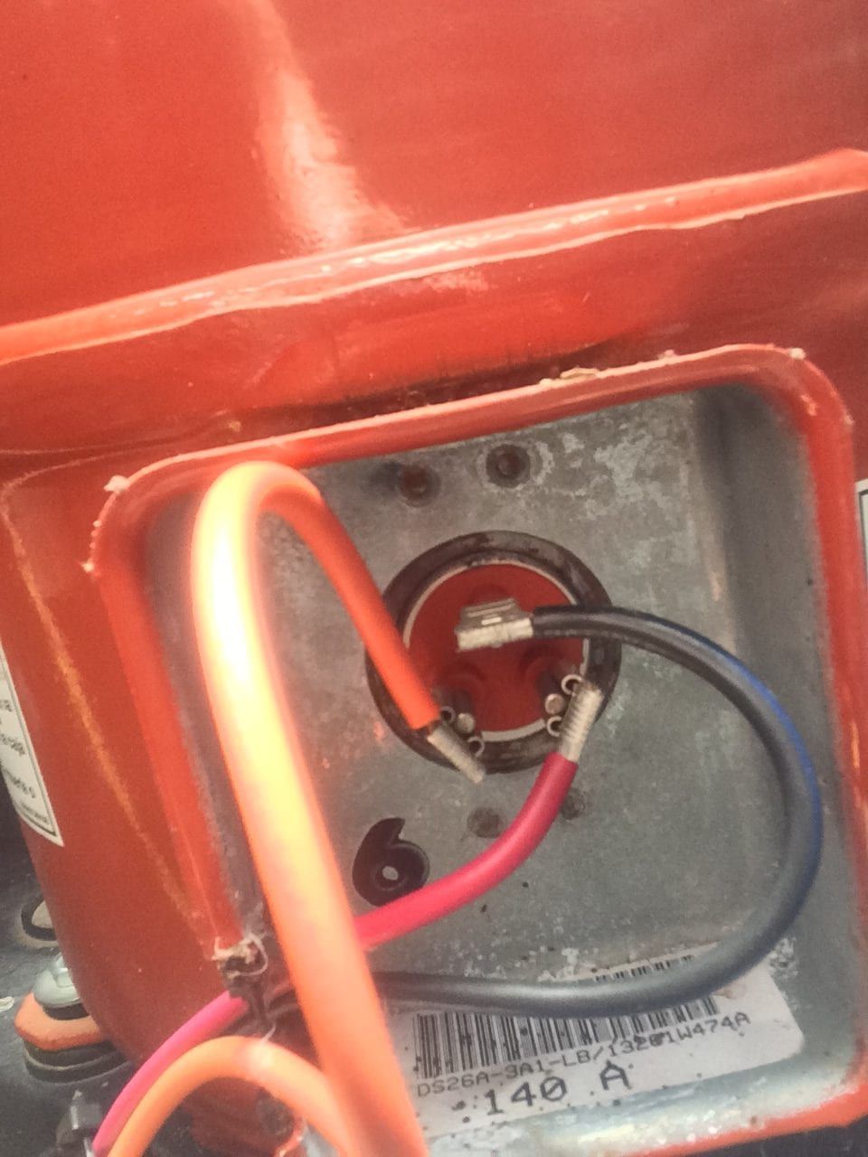
If you have ever had a single phase compressor that the terminals were not marked there is a fairly simple way to too identify which terminal is Common (C), Start (S), and Run (R). First follow all safety precautions, make sure power is off and if the compressor is in a pressurized system, do not place the meter probes directly on the compressor terminals. If the terminals are damaged and the system is pressurized, disturbing them to take readings could cause them to blow out, causing injury. Second remove the three compressor wires from all components. Then using your meter measure across the three compressor leads to find the two terminals that have the highest resistance reading. The remaining terminal is the Common (C) winding terminal. Next put one of your meter leads on common that was just found and the other lead on one of the other two remaining terminals to find the next highest resistance measurement. This is the Start (S) winding terminal. The last remaining terminal is the Run (R) winding terminal.
- Terminals C to R have the lowest resistance.
- Terminals C to S have the next highest resistance.
- Terminals R to S have the highest resistance.
- Resistance from C to S + Resistance from C to R = Resistance R to S.
- Example: C to S is (3.0) and C to R is (0.5) and R to S is (3.5) (3.0 + 0.5) = 3.