
Technical Services logo with red banner and blue swoosh accents
249 VAN Launch Kit 249 VAN Consumer Brochure Smart Thermostat Sell Sheet 249 VAN Launch Kit

Unlock the Full Potential

View Quick Start Guide

This installation was on a 4-story home, and the tech had not yet gone to the basement to troubleshoot the “infinity” water source heat pump, as he was told he by the homeowner. He was in the attic at the infinity furnace above the 4th floor. He was getting his dcv in the proper range on his A and B green plug on the air handler, 3 to 4 vdc. His indoor board ohm reading was in range, 28k to 32 k. The tech ohmed out the A and B thermostat wires on the water source heat pump from the upstairs. His ohm reading was not in range of a normal infinity board. His reading was around 64.4k. The tech then made the long walk to the basement where the “geothermal heat pump” was located. Bingo. 

Now get out there and organize some zone wiring!

Zone equipment would be identified as indoor unit- blue black/ outdoor unit-blue green:
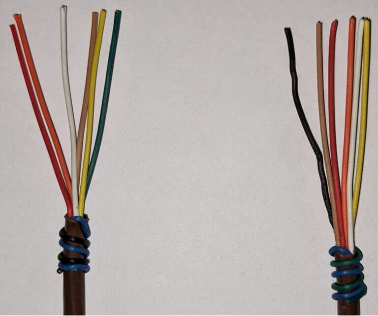
Close-up of two wrapped wire bundles with multicolored insulated strands on a white background
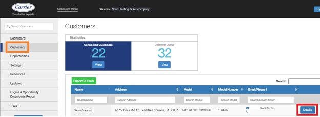
Customer dashboard with left navigation, blue summary tiles, and a highlighted button in the lower right.

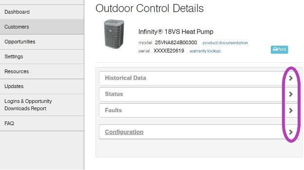
I have cropped some screens, and modified the serial numbers to keep certain dealer and customer’s information private. Setting the customers up on the portal is an easy process and could reap many benefits. Carrier and Bryant are going to begin utilizing this portal more with new upcoming equipment.


Get out there and get connected to the portal!
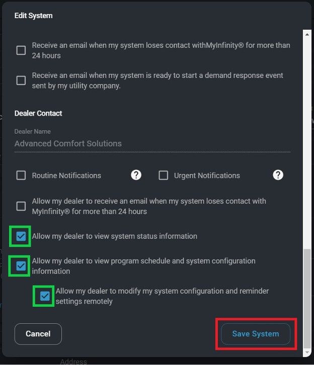
Dark settings dialog with checked notification options and a blue Save System button highlighted.
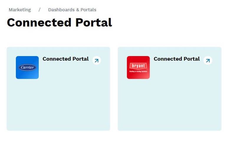
Dashboard showing two “Connected Portal” cards, one blue and one red, on a white page.
Outdoor Control Details page with sidebar menu and accordion sections highlighted by purple arrows
Picture of Steven Simmons

Steven Simmons

Technical Services Manager Southwest District

October 13, 2022

Schematic Reading Basics

For those new to the field, do you find it intimidating when you have to rely on the wiring schematic on a unit to figure out what a device is or what it should do? Or do you sometimes get confused looking at all the endless lines, weird symbols, and acronyms?


I’ll be first in line to tell you I shared those same feelings when I started my HVAC career. I am going to share some basics to reading Residential Wiring schematics with you in the article. The cool thing is almost all symbols are the same across all brands, and TYPICALLY the details within the symbols have a meaning, but every now and again the symbol will be generic and you will have to add in context clues to determine what they are.


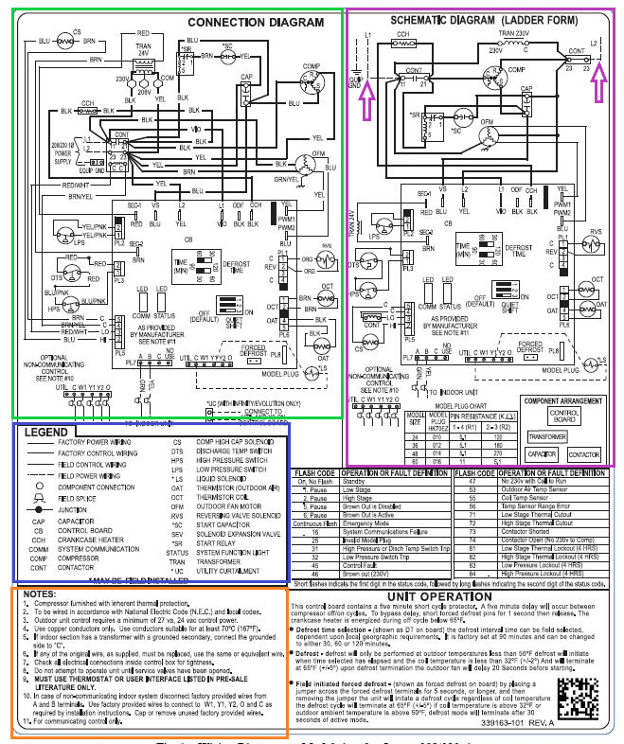
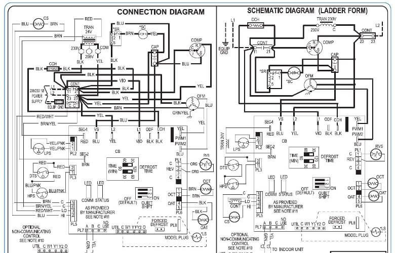
Let’s dive right in… Typical Residential Carrier wirings diagrams resemble this:

Split-page technical wiring diagram with dense black text and circuit schematics, outlined in green, red, blue, and orange.

Drawings in this article are from two Carrier manuals:25HNB9---2W & 50VR---07SI

The Connection Diagram is best used when you need to know exactly where the high voltage wires are terminated, the Ladder form is best when trying to figure out how power flows from L1 to L2 through the devices- I have added two arrows to indicate L1 & L2.


Legend–ANYTIME you have an acronym (which is where a word or group of words are shortened into just a few letters) the full meaning can always be found here.


Notes– Periodically you will see “see note x” on a diagram, refer to this area for details pertaining to the area dictating the note.


Symbols


Okay, now let’s break down some common symbols:

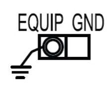
Ground symbol connected to labeled terminal marked “EQUIP GND” on a black-and-white diagram.

This symbol is for an equipment ground- almost any time you see three lines parallel either horizontally or vertically- they will mean earth/ ground.

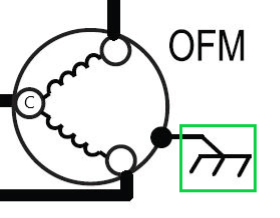
Black-and-white OFM diagram with circles, wavy lines, and a green highlight box on the right

Here is an Outdoor Fan Motor where you can see it contains two windings, Start and Run. Also, in green is another symbol for ground

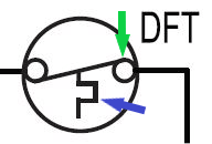
Diagram of a circular valve with black piping, green downward arrow, blue arrow, and “DFT” label.

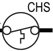
This is a DeFrost Thermostat. This zig-zag line means temperature. TYPICALLY, if you look at the right bubble on limits: if the line lands on top then it means “close on drop and open on rise” and if it’s on the bottom then it would mean “close on rise and open on drop” Remember this!

Black-and-white CHS logo with a circle, line, and small geometric shapes

This is a CrankCase Heater- According to the description above: it will open on temperature rise.


Let’s add more to this same rule

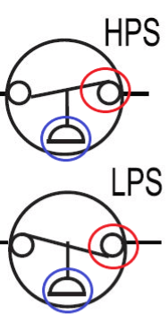
Two simple line diagrams labeled HPS and LPS with red and blue circles highlighting different parts.

Without looking up the acronyms I want to break these down.


Anytime you see these half circles they mean pressure. With this known, we can now see that the top switch will “open on pressure rise”- this is a High-Pressure Switch and the bottom will “open on pressure drop”- it is a Low-Pressure Switch.

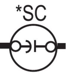
Black-and-white electrical symbol labeled “*SC” inside a circle, with a horizontal line and connector icons.

Lastly, if you see a backwards “C” next to a straight line like is presented here, then it is a capacitor. Some drawings will rotate this symbol so it will then look like a “U” and a flat line. This particular one is a Start Capacitor.


Now, keep this basic knowledge memorized and build onto it. Take a look at the close-up diagrams below and look for the symbols we just discussed and see how they interact with the electrical system.

Black-and-white electrical wiring diagram with connection and schematic labels side by side
249 VAN Launch Kit 249 VAN Consumer Brochure Smart Thermostat Sell Sheet 249 VAN Launch Kit

Unlock the Full Potential

View Quick Start Guide

This installation was on a 4-story home, and the tech had not yet gone to the basement to troubleshoot the “infinity” water source heat pump, as he was told he by the homeowner. He was in the attic at the infinity furnace above the 4th floor. He was getting his dcv in the proper range on his A and B green plug on the air handler, 3 to 4 vdc. His indoor board ohm reading was in range, 28k to 32 k. The tech ohmed out the A and B thermostat wires on the water source heat pump from the upstairs. His ohm reading was not in range of a normal infinity board. His reading was around 64.4k. The tech then made the long walk to the basement where the “geothermal heat pump” was located. Bingo. 


More to Explore

Family relaxing in a bright living room, parents on a gray couch with laptops while children play nearby
By Austin Sims August 4, 2026
At Mingledorff's we understand your business. We are your #1 HVAC and plumbing distributor choice. Trust our experience. Contact us today!
Mingledorffs
By Jenny Reed August 4, 2026
At Mingledorff's we understand your business. We are your #1 HVAC and plumbing distributor. Trust our experience. Contact us today!
Bright hobby shop with display cases, counter, and model kits; a few people stand near the back.
By Jenny Reed August 3, 2026
At Mingledorff's we understand your business. We are your #1 HVAC and plumbing distributor. Trust our experience. Contact us today!
Bright hobby shop interior with display cases, model kits, and a counter with two people inside.
By Jenny Reed August 3, 2026
At Mingledorff's we understand your business. We are your #1 HVAC and plumbing distributor. Trust our experience. Contact us today!

Heat Pump

Keep up with the latest HVAC news from Mingledorff’s Inc.