



Technical Services logo with red banner and blue swoosh accents
249 VAN Launch Kit 249 VAN Consumer Brochure Smart Thermostat Sell Sheet 249 VAN Launch Kit

Unlock the Full Potential

View Quick Start Guide

This installation was on a 4-story home, and the tech had not yet gone to the basement to troubleshoot the “infinity” water source heat pump, as he was told he by the homeowner. He was in the attic at the infinity furnace above the 4th floor. He was getting his dcv in the proper range on his A and B green plug on the air handler, 3 to 4 vdc. His indoor board ohm reading was in range, 28k to 32 k. The tech ohmed out the A and B thermostat wires on the water source heat pump from the upstairs. His ohm reading was not in range of a normal infinity board. His reading was around 64.4k. The tech then made the long walk to the basement where the “geothermal heat pump” was located. Bingo. 

Picture of Bubba Moore

Bubba Moore

Technical Services Manager Southeast District

August 12, 2021

Measuring Airflow Using Temperature Rise Method

What is airflow in a heating and cooling system? Why do we need to know what the airflow of a heating or cooling system is? Airflow is the amount of air measured in cubic feet per minute (CFM) that a system can deliver or move depending on its size. This CFM of a system is normally around 400 to 450 CFMs per ton of air. This can vary depending on the efficiency of the system. The reason we need to know the airflow of the system is to make sure that the system is performing as it was designed. Too much or too little airflow can affect comfort and cause equipment failures.


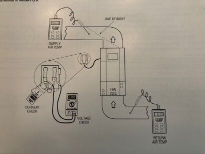
There are different methods of measuring airflow. The temperature rise method is fairly easy to use when measuring the CFMs on fan coils with electric heat. You will measure the amount of temperature rise across the electric heat elements, and also measure the voltage supplying the system, as well as the current flow or amps of the fan coil. The fan coil blower and electric elements will have to run continuously while preforming these measurements. Before taking any temperature readings or other measurements, make sure that the air filter is clean, and that all supply and return vents are opened and not blocked. Also, let the system run until the temperatures stabilize. Once the temperatures stabilize, measure the return air and supply air temperatures with an accurate electronic thermometer. Do not get your temperature reading above the electric elements. Make sure that these readings are down the duct or out of the line of sight of the electric elements.

Black-and-white electrical wiring diagram with labeled components, connectors, and arrows showing current flow.

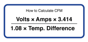
After the measurements have been gathered, this data will be plugged into a formula to see what airflow (CFMs) the system is producing. The formula is: Airflow (CFM) equals volts times amps times 3.414 (BTUs per watt) divided by 1.08 times the temperature difference of the supply and return air.

Formula card: “How to Calculate CFM” with Volts × Amps × 3.414 over 1.08 × Temp. Difference.

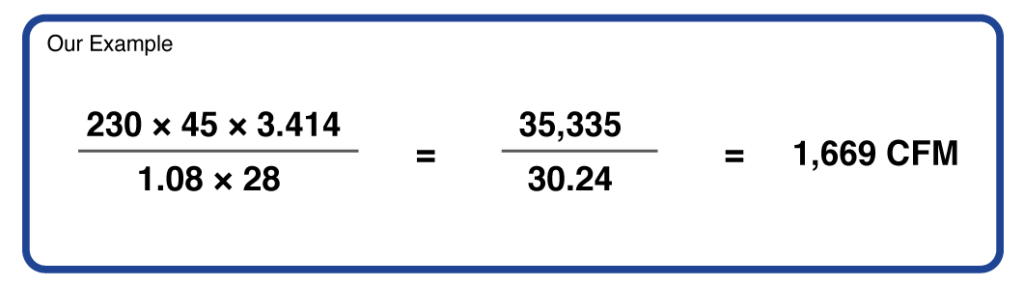
Using 400 CFMs per ton, this airflow calculation would be close to 3 Tons of airflow.

White calculation box showing a formula converting 230×45×3.414 divided by 1.08×28 to 1,669 CFM.

This simple calculation could help prove whether or not the problem is related to airflow. There may be a collapsed duct, or insulation inside of the duct may have come loose. If there was an equipment failure, this CFM test could prove why the equipment failed. It could also prove that airflow was not the problem and help point to a different reason for the failure.


Sources: HVAC Services Procedures

249 VAN Launch Kit 249 VAN Consumer Brochure Smart Thermostat Sell Sheet 249 VAN Launch Kit

Unlock the Full Potential

View Quick Start Guide

This installation was on a 4-story home, and the tech had not yet gone to the basement to troubleshoot the “infinity” water source heat pump, as he was told he by the homeowner. He was in the attic at the infinity furnace above the 4th floor. He was getting his dcv in the proper range on his A and B green plug on the air handler, 3 to 4 vdc. His indoor board ohm reading was in range, 28k to 32 k. The tech ohmed out the A and B thermostat wires on the water source heat pump from the upstairs. His ohm reading was not in range of a normal infinity board. His reading was around 64.4k. The tech then made the long walk to the basement where the “geothermal heat pump” was located. Bingo. 


More to Explore

Family relaxing in a bright living room, parents on a gray couch with laptops while children play nearby
By Austin Sims August 4, 2026
At Mingledorff's we understand your business. We are your #1 HVAC and plumbing distributor choice. Trust our experience. Contact us today!
Mingledorffs
By Jenny Reed August 4, 2026
At Mingledorff's we understand your business. We are your #1 HVAC and plumbing distributor. Trust our experience. Contact us today!
Bright hobby shop with display cases, counter, and model kits; a few people stand near the back.
By Jenny Reed August 3, 2026
At Mingledorff's we understand your business. We are your #1 HVAC and plumbing distributor. Trust our experience. Contact us today!

Bright hobby shop interior with display cases, model kits, and a counter with two people inside.
By Jenny Reed August 3, 2026
At Mingledorff's we understand your business. We are your #1 HVAC and plumbing distributor. Trust our experience. Contact us today!


Heat Pump

Keep up with the latest HVAC news from Mingledorff’s Inc.