
Unlock the Full Potential
This installation was on a 4-story home, and the tech had not yet gone to the basement to troubleshoot the “infinity” water source heat pump, as he was told he by the homeowner. He was in the attic at the infinity furnace above the 4th floor. He was getting his dcv in the proper range on his A and B green plug on the air handler, 3 to 4 vdc. His indoor board ohm reading was in range, 28k to 32 k. The tech ohmed out the A and B thermostat wires on the water source heat pump from the upstairs. His ohm reading was not in range of a normal infinity board. His reading was around 64.4k. The tech then made the long walk to the basement where the “geothermal heat pump” was located. Bingo.
Now get out there and organize some zone wiring!
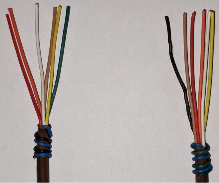
Zone equipment would be identified as indoor unit- blue black/ outdoor unit-blue green:
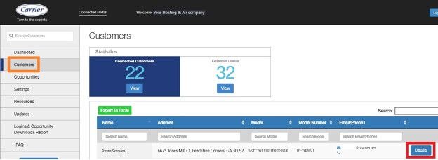
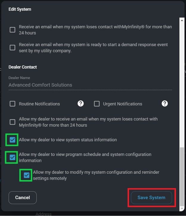
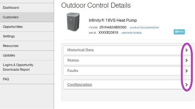
I have cropped some screens, and modified the serial numbers to keep certain dealer and customer’s information private. Setting the customers up on the portal is an easy process and could reap many benefits. Carrier and Bryant are going to begin utilizing this portal more with new upcoming equipment.
Get out there and get connected to the portal!
*Wiring diagrams highlighted with colors chosen for high contrast- not for wire color designation*
Low voltage starts in the red box at the transformer, 24vac goes to the Indoor Fan Board (IFB), through a fuse and on to the thermostat. Depending on what the thermostat calls for, 24vac will be sent down a different wire(s) to turn on/off the multiple devices in the system. The other low voltage wire (C) has an unbroken path to EVERY component in the unit. I have highlighted the pathway in blue and circled each component in purple. This wire/path is something each device has in “common”—it is the common wire. In layman’s terms, the common wire is the return pathway for voltage to come back to the transformer since it left out on the 24vac side.
The Common wire/terminal is always the one thing that is relatable or in common with the surrounding wires/terminals. Relays, motors, control boards, and even transformers all have some type of common wire/terminal. Common for a relay isn’t the same as common on a motor, but within each given device they carry the same meaning. Now go back and reread the second paragraph above—it will have a deeper meaning now.
Challenge: Check out the high voltage side of the Transformer. It has a COM terminal…. it’s not low voltage common. What is it?
That’s all.

Loading PDF…
Unable to Load PDF
Please check the URL and try again.
September 2, 2021
ABB Drives: How to Set Up on a Light Commercial System
Commercial HVAC
Have you seen an ABB Variable Frequency Drive or VFD for short?
Odds are if you have installed or serviced a light commercial HVAC system in the last few years then you have come across one of these drives. The first thing you will notice is that the VFD does not come with a key pad because under normal operations a keypad is not needed. Test and balance DO NOT need this keypad and they should make airflow adjustments with the sheaves on the motor.
Keypad Assistance?
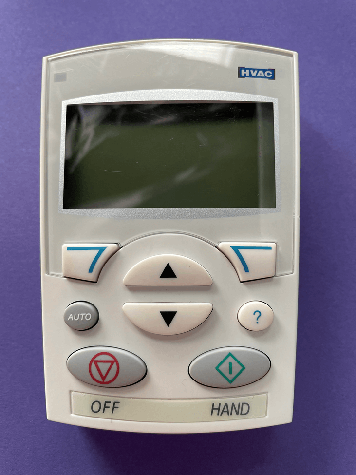
When you first plug in the keypad it will prompt you for assistance. Choose “No”. The drives already have a program in them and they need a few parameters to be set. If assistance is chosen, it will make changes to the programing of the drive. If “yes” is chosen for assistance then you have to go to parameter 9902, change it to something other than HVAC and save it. Then edit the parameter back to HVAC and save it again. Go to parameter 1611 and select “Long View.” After that you can proceed with the parameter setup.
ABB VFD Models
Carrier/Bryant is utilizing two different models of the ABB brand drives on the light commercial platform: ACS320 and ACH550.
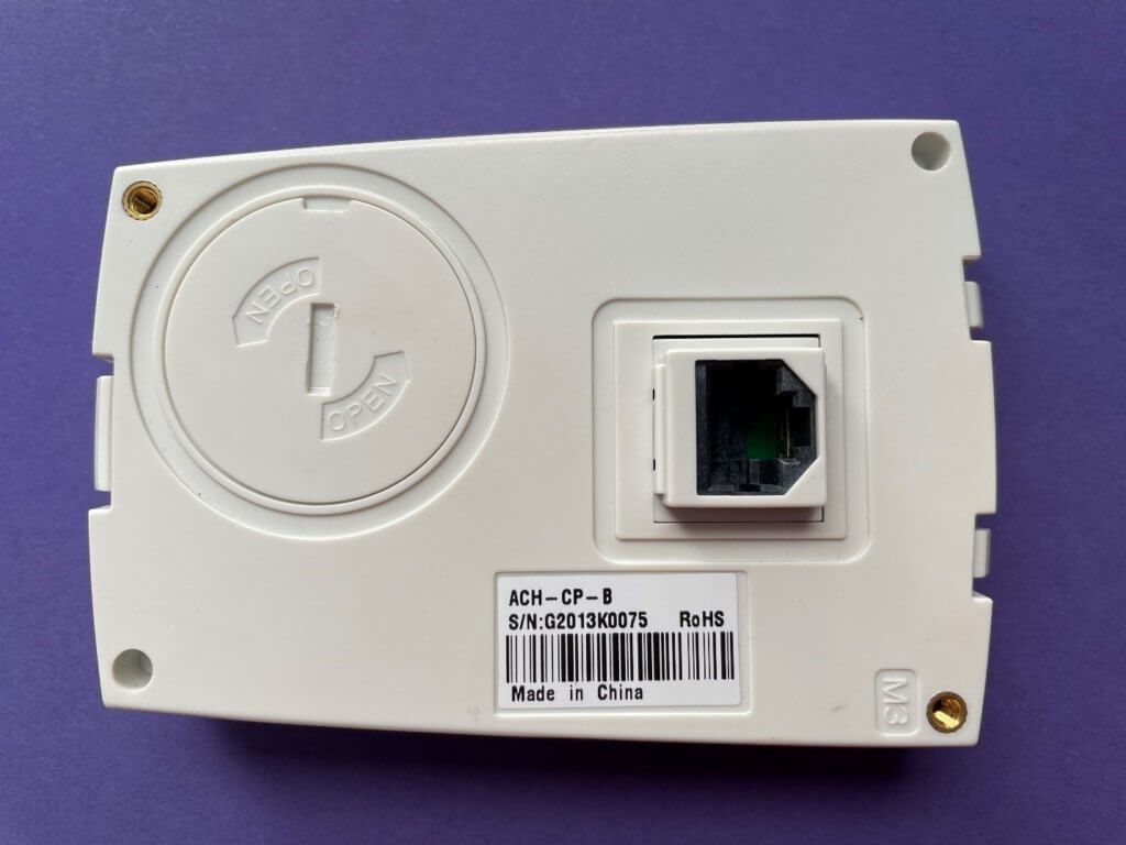
There are also two different Keypads: ACH-CP-B and CAR-CP-H.
The CAR-CP-H ONLY works on the ACH550.
The ACH-CP-B works on BOTH drives and is the newest keypad.
Your keypad model can be found on the back.

VFD Failure and Replacement
After a drive has failed and has been replaced you have two options when it comes to setting up the drive: Upload/Download or Manual Parameter Setup.
Upload/Download:
- Can ONLY be used when you have the EXACT same unit model number to upload the parameters from as the unit model number that has the failed drive.
To UPLOAD:
Turn off- Press bottom left button
Menu- Press top right button
Par back up / Press enter on top right
Upload to panel—Press SEL top right
When finished: Press OK on top left
Press Exit on top left (press 2 times)
Turn back to auto (Press round button)
To DOWNLOAD:
Turn off– Press bottom left button
Menu– Press top right button
Par Back up / Press enter on top right
Download full set– Press SEL top right
When finish: Press OK on top left
Press Exit on top left Press 2 times
Turn back to auto (Press round button)
Manual Parameter Setup:
To perform a manual setup, use the book that came with the keypad to locate the page with your unit model number on the top and choose the page that has the correct drive number and motor model number. Double check that the HP and voltage are correct. Use the parameter settings and proceed:
To Access Parameters:
Turn off- Press bottom left button
Menu- Press top right button
Parameters / Press enter on top right
Select desired category 01-99/ Press SEL on top right
Select Desired Parameter/ Press EDIT on top right
Make needed changes/ Press SAVE on top right
Go to next Parameter OR Press exit to choose another category
After completion Press Exit on top left Press 3 times
Turn back to AUTO (Press round button)
Helpful Hints:
- Drives MUST be “off” to make changes to parameters
- Remember to put drive in “auto” BEFORE unplugging keypad
- Categories are just the first two numbers of the parameter number
Example: Parameters 9905 and 9906 will be in category 99
- Take pictures of the wiring of the controls on the old drive before unwiring it
Watch the Video Below for a Demonstration

Unlock the Full Potential
This installation was on a 4-story home, and the tech had not yet gone to the basement to troubleshoot the “infinity” water source heat pump, as he was told he by the homeowner. He was in the attic at the infinity furnace above the 4th floor. He was getting his dcv in the proper range on his A and B green plug on the air handler, 3 to 4 vdc. His indoor board ohm reading was in range, 28k to 32 k. The tech ohmed out the A and B thermostat wires on the water source heat pump from the upstairs. His ohm reading was not in range of a normal infinity board. His reading was around 64.4k. The tech then made the long walk to the basement where the “geothermal heat pump” was located. Bingo.
More to Explore
Heat Pump
Keep up with the latest HVAC news from Mingledorff’s Inc.