Unlock the Full Potential
This installation was on a 4-story home, and the tech had not yet gone to the basement to troubleshoot the “infinity” water source heat pump, as he was told he by the homeowner. He was in the attic at the infinity furnace above the 4th floor. He was getting his dcv in the proper range on his A and B green plug on the air handler, 3 to 4 vdc. His indoor board ohm reading was in range, 28k to 32 k. The tech ohmed out the A and B thermostat wires on the water source heat pump from the upstairs. His ohm reading was not in range of a normal infinity board. His reading was around 64.4k. The tech then made the long walk to the basement where the “geothermal heat pump” was located. Bingo.
Now get out there and organize some zone wiring!
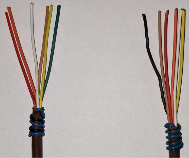
Zone equipment would be identified as indoor unit- blue black/ outdoor unit-blue green:
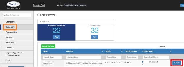
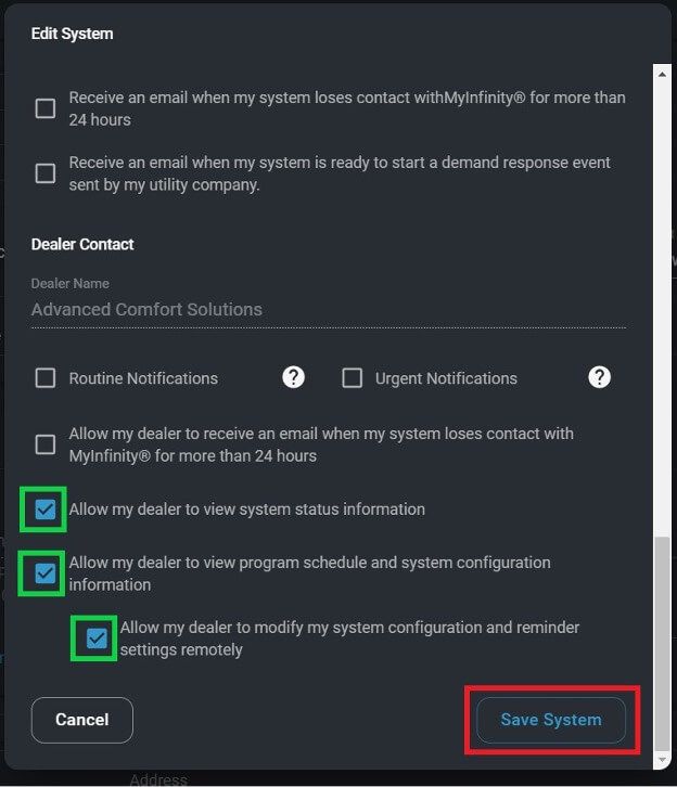
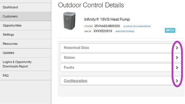
I have cropped some screens, and modified the serial numbers to keep certain dealer and customer’s information private. Setting the customers up on the portal is an easy process and could reap many benefits. Carrier and Bryant are going to begin utilizing this portal more with new upcoming equipment.
Get out there and get connected to the portal!
These units are more complex and have more variables to consider.
*to keep things simple, we typically round close decimal numbers*
Min. Piping Length per each indoor unit- This is the minimum allowed amount of lineset for each indoor unit
Standard Piping Length per each indoor unit- this is the amount of lineset that has been “reserved” for each indoor unit for refrigerant charge purposes.
Max. outdoor-indoor height difference- how far you can separate the indoor from the outdoor vertically. Two labels are shown- IU indoor unit above OU outdoor unit and vice versa.
Max. height different between indoor units- if the indoor units are on different levels, then they should not exceed this amount of vertical separation amongst themselves.
Max. Length per each indoor unit- no indoor unit should have a lineset longer than this number. Do not exceed this number for any indoor unit lineset.
Max. Piping Length with no additional refrigerant charge- add together all of the lineset lengths for all the indoor units. If your lengths are above this number, then additional charge is needed.
Total Maximum Piping Length per system– when adding together all the indoor pipe lengths, this is the total length that the unit can support. Pipe lengths greater than this are not approved nor recommended.
Additional refrigerant charge- if your total lineset length is over the “Max. Piping Length with no additional refrigerant charge” amount, this is how many ounces per foot should be added to the unit for proper operation.
Pipe sizes: these show the pipe sizes with an asterisk (*) and then the quantity of those ports.
For example: from the 36K– 1/2 *2+3/8*2
This means 2 at ½ and 2 at 3/8.
In the event that the correct line set size is ran and it is not the same size as the hookup of this unit, use the factory supplied adapters to make the connections.
*Wiring diagrams highlighted with colors chosen for high contrast- not for wire color designation*
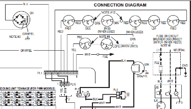
Low voltage starts in the red box at the transformer, 24vac goes to the Indoor Fan Board (IFB), through a fuse and on to the thermostat. Depending on what the thermostat calls for, 24vac will be sent down a different wire(s) to turn on/off the multiple devices in the system. The other low voltage wire (C) has an unbroken path to EVERY component in the unit. I have highlighted the pathway in blue and circled each component in purple. This wire/path is something each device has in “common”—it is the common wire. In layman’s terms, the common wire is the return pathway for voltage to come back to the transformer since it left out on the 24vac side.
The Common wire/terminal is always the one thing that is relatable or in common with the surrounding wires/terminals. Relays, motors, control boards, and even transformers all have some type of common wire/terminal. Common for a relay isn’t the same as common on a motor, but within each given device they carry the same meaning. Now go back and reread the second paragraph above—it will have a deeper meaning now.
Challenge: Check out the high voltage side of the Transformer. It has a COM terminal…. it’s not low voltage common. What is it?
That’s all.
If a Wi-fi Network security key is shown as in the picture below enter the key and press Next.
The Iron Controller will inform you if the wi-fi connection was successful. Click Done