
Unlock the Full Potential
This installation was on a 4-story home, and the tech had not yet gone to the basement to troubleshoot the “infinity” water source heat pump, as he was told he by the homeowner. He was in the attic at the infinity furnace above the 4th floor. He was getting his dcv in the proper range on his A and B green plug on the air handler, 3 to 4 vdc. His indoor board ohm reading was in range, 28k to 32 k. The tech ohmed out the A and B thermostat wires on the water source heat pump from the upstairs. His ohm reading was not in range of a normal infinity board. His reading was around 64.4k. The tech then made the long walk to the basement where the “geothermal heat pump” was located. Bingo.
2. The second in SEER sequence is the HP 20 SEER/ AC 20.5 SEER. It has two nicknames: Greenspeed/ Extreme & 1st Gen Greenspeed/ 1st Gen Extreme. It is recognized by have the inverter at the top in a black box, with 3 items below it: control board, transformer, and a contactor.
- Inverter made by Emerson
- Typically, 40%-100% all variable
- Scroll compressors
- Outdoor fan motor is ECM
- Model numbers: 25VNA0/ 24VNA0 & 280ANV/180CNV
Now get out there and organize some zone wiring!
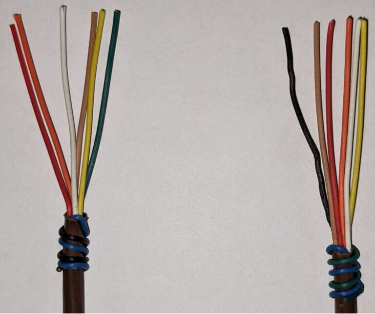
Zone equipment would be identified as indoor unit- blue black/ outdoor unit-blue green:
How do you know the system has been adequately evacuated? First, the system needs to be vacuumed to 500 microns or below, then it is isolated from the vacuum pump. Now the vacuum gauge needs to be monitored to see if there are any changes in the level of vacuum in the system. If the vacuum gauge shows a pressure rise and the pressure continues to rise without leveling off, a leak exists somewhere and needs to be located and repaired.
If the vacuum gauge shows a pressure rise and levels off between1,000 and 2,000 microns within seven minutes, the system is leak free but still too wet. A constant reading on the vacuum gauge of 500 to a 1,000 microns within seven minutes indicates a tight leak free dry system.
The Triple Vacuum Method
The triple evacuation method can take about three hours when performed as recommended. The system is first evacuated to 5,000 microns during the first and second evacuations. Between the evacuations, the system is pressurized with dry nitrogen to about 10 psig and allowed to sit for an hour so the nitrogen can absorb the moisture. For the third and last evacuation, a deep vacuum of 500 microns is preformed and the system is monitored in the same manner described for the deep vacuum method.

May 1, 2020
Compressor Protector – The Comfort Alert Module
HVAC Compressor
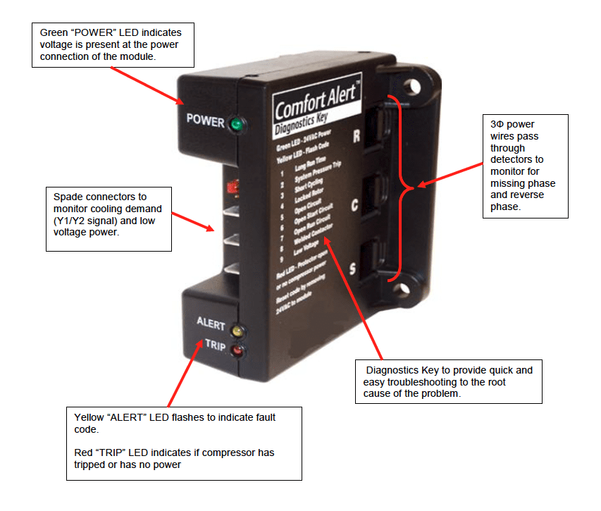
The C.A.M. protects your 3 phase scroll HVAC compressor from nine separate system issues.
The board has nine LED diagnostic alert codes that indicate a system condition by indicator flashes on the module. The flashing LED indicator communicates the alert code and prompts the service technician to more quickly and accurately conduct troubleshooting on Carrier and Bryant condensing units.
The Comfort Alert™ diagnostics module is an innovation for troubleshooting and protecting three phase scroll compressors used in Carrier’s new condensing units and heat pumps. All of Carrier’s 6 thru 20 ton condensing units and heat pumps have this controller as a standard feature, mounted in the control box. The Comfort Alert uses the compressor & system sensors to monitor and analyze system performance. The controller is completely self-contained and mounts in the condensing unit or heat pump. The board has nine LED diagnostic alert codes that indicate a system condition by L.E.D. indicator flashes on the module. The flashing LED indicator communicates the alert code and prompts the service technician to more quickly and accurately conduct troubleshooting on Carrier’s condensing units.
RED & GREEN LEDS FOR HVAC COMPRESSOR PROTECTION
The module provides three phase compressor protection and will shut down the compressor when potential damaging conditions are detected including missing and reverse phase. There is a Green LED indicator that voltage is present at the Power Connection of the module. There is a Yellow LED indicator that flashes nine different fault codes. This unique code will flash a number of times consecutively, pause and then repeat the process. The number of consecutive flashes, which is defined as the Flash Code, corresponds to a fixed abnormal condition;
- Long Run Time
- System Pressure Trip
- Short Cycling
- Locked Rotor
- Open Circuit
- Open Start Circuit
- Open Run Circuit
- Welded Contactor
- Low Voltage
There is also a Red LED indicator that the compressor has tripped or has no power. The trip Red LED indicates that there is a demand signal from the thermostat or sensor but no current to the compressor is detected by the module. A flashing Red LED indicates the anti-short cycle timer is active, preventing the compressor from starting.


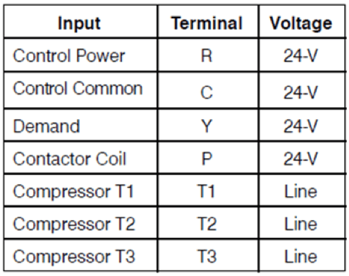
Terminal Designations
Unlock the Full Potential
This installation was on a 4-story home, and the tech had not yet gone to the basement to troubleshoot the “infinity” water source heat pump, as he was told he by the homeowner. He was in the attic at the infinity furnace above the 4th floor. He was getting his dcv in the proper range on his A and B green plug on the air handler, 3 to 4 vdc. His indoor board ohm reading was in range, 28k to 32 k. The tech ohmed out the A and B thermostat wires on the water source heat pump from the upstairs. His ohm reading was not in range of a normal infinity board. His reading was around 64.4k. The tech then made the long walk to the basement where the “geothermal heat pump” was located. Bingo.
More to Explore
Heat Pump
Keep up with the latest HVAC news from Mingledorff’s Inc.