
Unlock the Full Potential
This installation was on a 4-story home, and the tech had not yet gone to the basement to troubleshoot the “infinity” water source heat pump, as he was told he by the homeowner. He was in the attic at the infinity furnace above the 4th floor. He was getting his dcv in the proper range on his A and B green plug on the air handler, 3 to 4 vdc. His indoor board ohm reading was in range, 28k to 32 k. The tech ohmed out the A and B thermostat wires on the water source heat pump from the upstairs. His ohm reading was not in range of a normal infinity board. His reading was around 64.4k. The tech then made the long walk to the basement where the “geothermal heat pump” was located. Bingo.
Now get out there and organize some zone wiring!
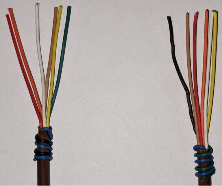
Zone equipment would be identified as indoor unit- blue black/ outdoor unit-blue green:
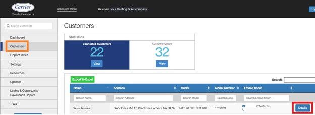
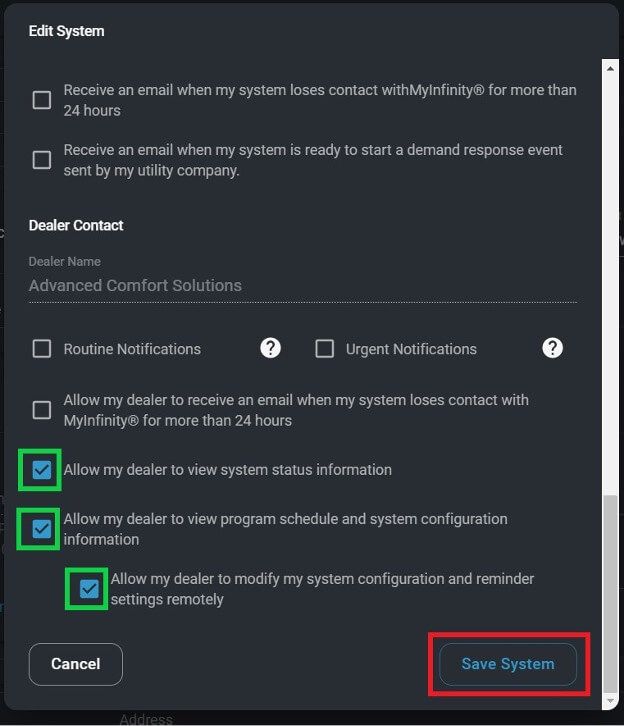
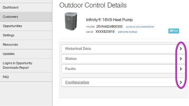
I have cropped some screens, and modified the serial numbers to keep certain dealer and customer’s information private. Setting the customers up on the portal is an easy process and could reap many benefits. Carrier and Bryant are going to begin utilizing this portal more with new upcoming equipment.
Get out there and get connected to the portal!
*Wiring diagrams highlighted with colors chosen for high contrast- not for wire color designation*
Low voltage starts in the red box at the transformer, 24vac goes to the Indoor Fan Board (IFB), through a fuse and on to the thermostat. Depending on what the thermostat calls for, 24vac will be sent down a different wire(s) to turn on/off the multiple devices in the system. The other low voltage wire (C) has an unbroken path to EVERY component in the unit. I have highlighted the pathway in blue and circled each component in purple. This wire/path is something each device has in “common”—it is the common wire. In layman’s terms, the common wire is the return pathway for voltage to come back to the transformer since it left out on the 24vac side.
The Common wire/terminal is always the one thing that is relatable or in common with the surrounding wires/terminals. Relays, motors, control boards, and even transformers all have some type of common wire/terminal. Common for a relay isn’t the same as common on a motor, but within each given device they carry the same meaning. Now go back and reread the second paragraph above—it will have a deeper meaning now.
Challenge: Check out the high voltage side of the Transformer. It has a COM terminal…. it’s not low voltage common. What is it?
That’s all.

Loading PDF…
Unable to Load PDF
Please check the URL and try again.
February 9, 2021
Using a Standard Thermostat with a Communicating System for Emergency Operation
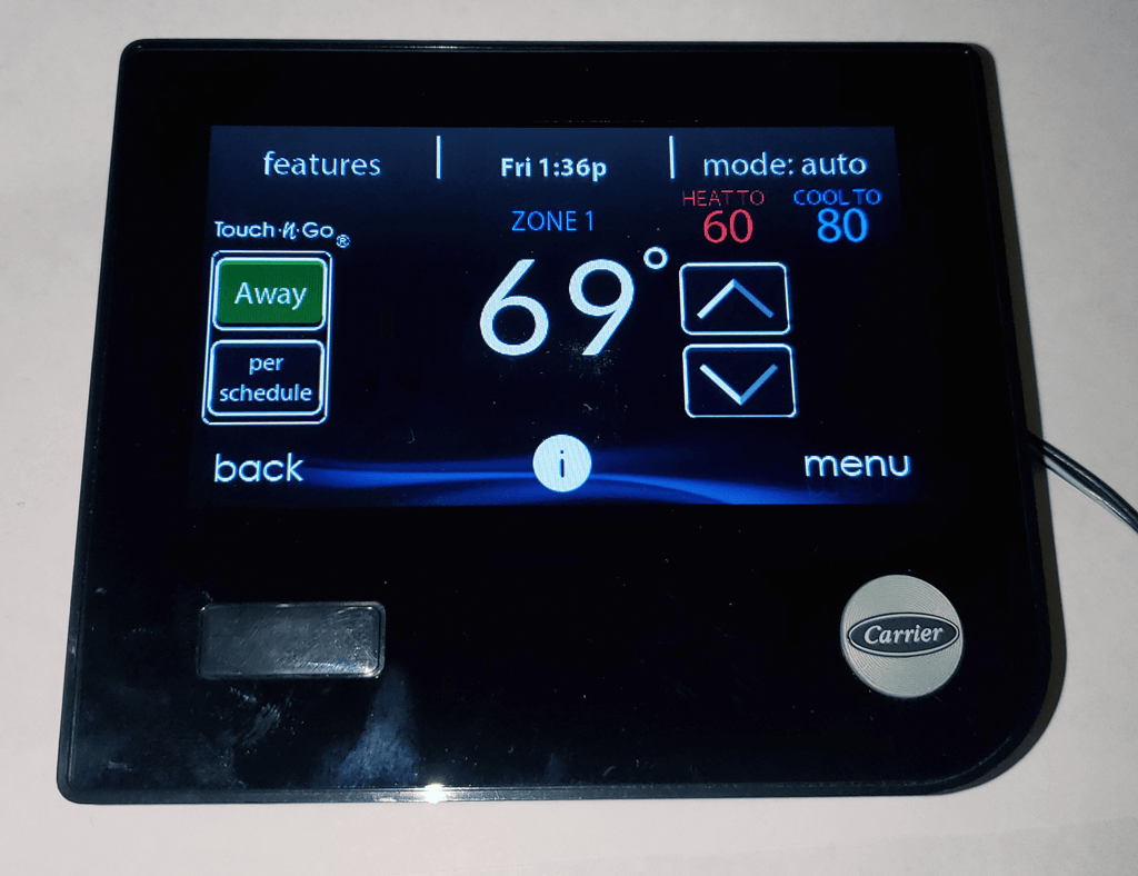
On rare occasions the infinity wall controllers fail. Sometimes, this failure is after hours and the supply house is closed. Periodically, homeowners do not want to purchase another wall controller due to cost and they researched their unit on the web and read that a “regular or standard” thermostat will work their Infinity system.
I have to say first, that it is highly recommended that Infinity series equipment be used with an Infinity wall control; this way all the features of the unit the customer initially bought can be utilized and when there is a malfunction it is communicated to all the equipment to better protect against further damage. The installation manual provided from Carrier for the FE4A/FE5A does NOT show an option for wiring a standard Thermostat nor Thermidistat to the fan coil, only an Infinity wall controller. Furthermore, ALL the manuals for outdoor Infinity equipment state that an Infinity wall controller MUST be used. All manuals do say however that a standard thermostat can be used to control the unit’s control boards using emergency operation modes. There is NO guarantee that it will work indefinitely because the terminals that will be used to wire the board are intended to be outputs for a non-communicating outdoor unit not inputs from a thermostat. If the unit is being ran in emergency operation with a standard thermostat then there will be no control of humidity, no air flow staging, and the unit will not provide the level of efficiency nor comfort that they were receiving with the Infinity wall controller. Carrier states in the FE4A/FE5A manual “(Emergency mode) should only be activated when User Interface cannot be replaced immediately”.
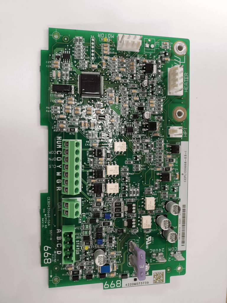
If through troubleshooting it is found that the wall controller is faulty and must be replaced, the wall controller should be changed and replaced with a newer model. If it happens to be after hours, on the weekend, a holiday, or the wall controller is not available, then the indoor and outdoor control boards will allow emergency heating and cooling operations using a standard thermostat. If the FE4A/FE5A control board does not have communication with a wall controller for a period exceeding two minutes then the unit will flash a code 16, system communication fault.
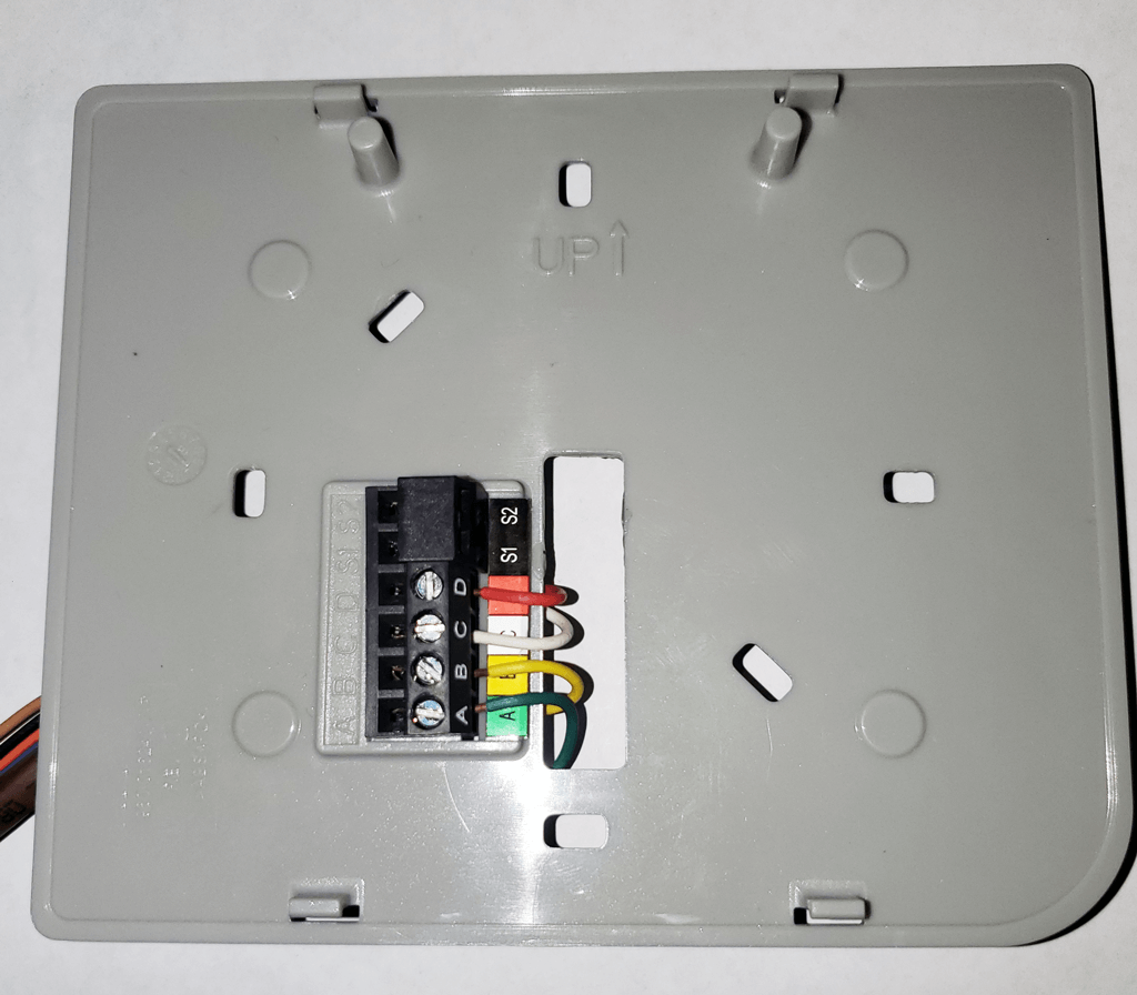
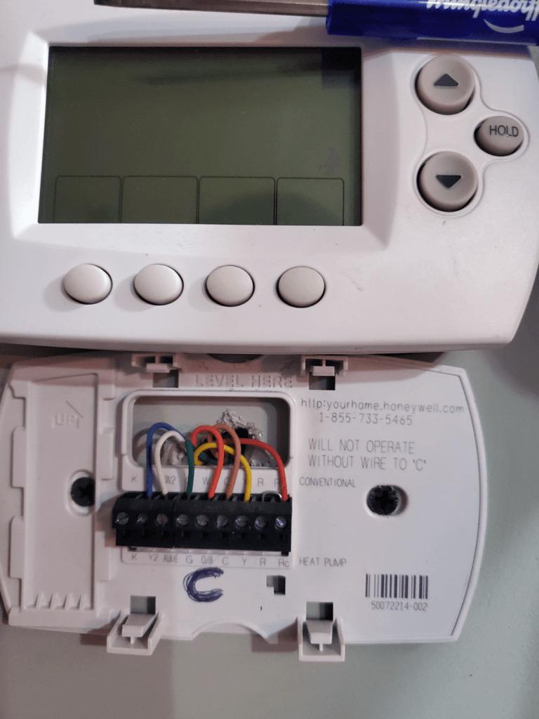
To utilize this emergency operation modes the thermostat, fan coil, and outdoor unit must be unwired from the ABCD terminals and be rewired for R, G, W, Y, O, C. When the unit is wired appropriately, the two-minute time period has lapsed, and the indoor is flashing a code 16 on the status LED the unit will start responding to the emergency inputs. If the indoor control board retains the tonnage of the outdoor equipment, then the indoor will provide the air flow of 350 CFM times the tonnage of the outdoor. If the indoor control board does retain the information of the outdoor equipment then the indoor board will provide 350 CFM per ton for the highest possible matched outdoor unit for each indoor unit size:
002: 1050 CFM; 003/004: 1225 CFM; 005:1400 CFM; 006:1750 CFM;


The thermostat should be programmed for either 2H/2C or 3H/2C depending on your outdoor equipment. Use the chart to wire the thermostat and follow from left to right to see where each wire will be terminated according to which model outdoor unit you have. The chart represents the latest models found in Carrier’s Catalog.
| Thermostat |
Fan coil |
Heat Pumps |
|||
| 3H/2C | FE4A | 25HNAB6/9 | 25VNA8 | 25VNA0 | 25VNA4 |
| R | R | R | |||
| C | C | C | C | C | C |
| O | O | O | O | O | O |
| Y1 | Y | Y1 | Y1 | Y | Y1 |
| Y2 | Y2 | Y2 | Y2 | ||
| G* | G* | ||||
| W2/AUX | W | W | W | W | |
| *not all indoor control boards have a G terminal | |||||
Unlock the Full Potential
This installation was on a 4-story home, and the tech had not yet gone to the basement to troubleshoot the “infinity” water source heat pump, as he was told he by the homeowner. He was in the attic at the infinity furnace above the 4th floor. He was getting his dcv in the proper range on his A and B green plug on the air handler, 3 to 4 vdc. His indoor board ohm reading was in range, 28k to 32 k. The tech ohmed out the A and B thermostat wires on the water source heat pump from the upstairs. His ohm reading was not in range of a normal infinity board. His reading was around 64.4k. The tech then made the long walk to the basement where the “geothermal heat pump” was located. Bingo.
More to Explore
Heat Pump
Keep up with the latest HVAC news from Mingledorff’s Inc.