
Technical Services logo with red banner and blue swoosh accents
249 VAN Launch Kit 249 VAN Consumer Brochure Smart Thermostat Sell Sheet 249 VAN Launch Kit

Unlock the Full Potential

View Quick Start Guide

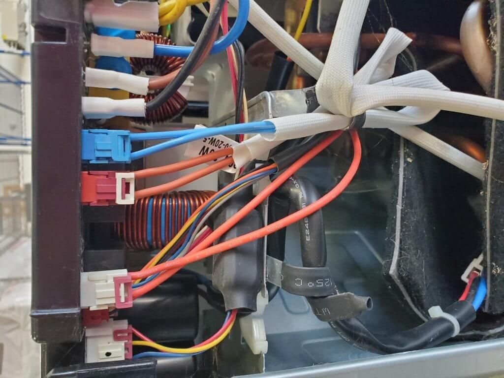
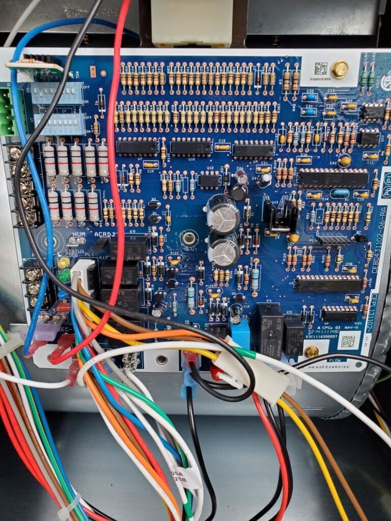
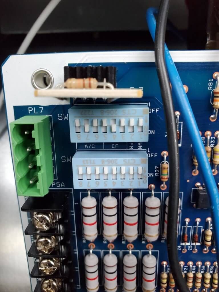
This installation was on a 4-story home, and the tech had not yet gone to the basement to troubleshoot the “infinity” water source heat pump, as he was told he by the homeowner. He was in the attic at the infinity furnace above the 4th floor. He was getting his dcv in the proper range on his A and B green plug on the air handler, 3 to 4 vdc. His indoor board ohm reading was in range, 28k to 32 k. The tech ohmed out the A and B thermostat wires on the water source heat pump from the upstairs. His ohm reading was not in range of a normal infinity board. His reading was around 64.4k. The tech then made the long walk to the basement where the “geothermal heat pump” was located. Bingo. 
Mingledorffs
Mingledorffs
Mingledorffs
Mingledorffs

If you see a fixed negative or a small amount of fluctuating volts staying in the negative, the indoor board has failed.


If you see a fixed positive volt reading or a fluctuating positive reading the outdoor board is bad.


The reactor also needs to be checked. Check the reactor with the wires off and ohm it out. The ohm reading should be .1-1 ohm and should not be grounded.

Picture of Jonathon Pullen

Bubba Moore

Technical Services Manager Southeast District

December 8, 2020

Thermocouple & Flame Rectification Sensor

Athermocouple is a safety device that is used on gas furnaces where the pilot is lit continuously, whether the main burner is on or off. The flame rectification sensor is a safety device used in high efficiency furnaces that use direct burner ignition. The thermocouple is used in older furnaces and is being phased out because of the inefficiency of the pilot burning all the time. The higher efficiency furnaces only have a flame burning when there is a demand for heat which improves the efficiency of the furnace.


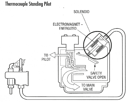
Thermocouples are used with a 100% shutoff gas valves. When there is insufficient pilot flame or a defective thermocouple, all gas is shut off through the main valve. When the pilot is heating up the thermocouple it produces a small DC voltage. This DC voltage energizes a solenoid in the gas valve that holds the safety valve open to keep gas flowing to the pilot. If the pilot goes out, the thermocouple cools and the voltage generated drops to zero. This causes the safety valve to close, shutting off the gas flow to the pilot and main gas valve. There are things to check before replacing the thermocouple. Look for a yellow pilot flame, pilot flame too small or low, misdirected pilot flame, a pilot flame that is flickering, pilot flame that is floating away from the thermocouple, or a pilot flame that is lifting away. Also inspect the thermocouple to see if it is bent, the lead is kinked, insulator is damaged, or thermocouple contact end is dirty.

Mingledorffs

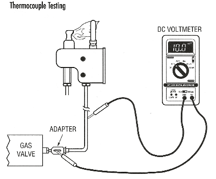
The thermocouple can be tested under load or no-load conditions using a volt ohm meter or a digital multi meter. To test a thermocouple under load, you will first unscrew the thermocouple and install a thermocouple test adapter, then screw the thermocouple into the adaptor. Connect one-meter lead to the adaptor and the other to the copper of the thermocouple. Make sure that your meter is set to the lowest DC millivolt setting. With the pilot burning for at least five minutes, the DC millivolt reading should be nine millivolts or higher. If not, the thermocouple is defective and needs replacing.

Mingledorffs

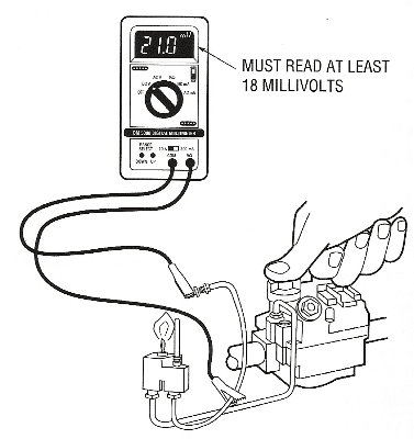
To perform the no load thermocouple test, no adaptor is needed. Connect one of your meter leads to the tip of the thermocouple that goes into the gas valve, the other lead connects to the copper of the thermocouple. With the pilot burning for at least five minutes, the DC millivolt reading should be eighteen millivolts or higher. The thermocouple is defective and needs to be replaced if the reading is below eighteen millivolts.

Mingledorffs

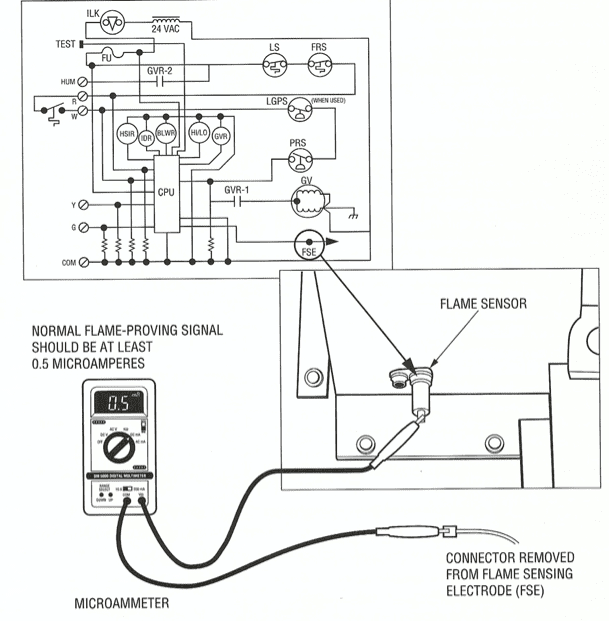
The flame rectification sensor is used in high efficiency furnaces that do not use a pilot flame. These furnaces use a hot surface ignition or direct spark ignition to light the main burners. The flame rectification sensor, also called flame sensing electrode or flame rod, is used to detect that the main burner flame is lite. As the burner flame passes across the flame rod, the hot gas ionized particles conduct electricity and completing a circuit through the flame rod to the furnace control. This current flow signals the furnace microprocessor to keep the gas valve energized. To test the flame rectification sensor, a meter that can measure DC microamps will be connected in series with the sensor. With the burners lit, the sensor input to the microprocessor should have a current of at least 0.5 microamps DC, though some furnaces may have a higher or lower flame sensing current. If the flame sensing current is low or not there, look to see how the flame rod is positioned in the burner flame. Check to see if the furnace is properly grounded per manufacturer’s instructions, the gas valve is grounded through the gas valve ground wire, connection at the sensor is good, and there is no oxide film coating the flame sensing electrode. If there is a coating on the electrode, clean with a fine abrasive. These are the most common problems to look for when troubleshooting the flame proving signal.

Flame sensor test diagram with microammeter and normal flame-proving signal shown in a boiler wiring schematic

The thermocouple and flame rectification sensor are two ways of proving a flame. One has a flame burning all the time to allow proper operations, and the other needs a flame to be lit to confirm there is a flame for proper operations.


Sources: HVAC Servicing Procedures Manual

249 VAN Launch Kit 249 VAN Consumer Brochure Smart Thermostat Sell Sheet 249 VAN Launch Kit

Unlock the Full Potential

View Quick Start Guide

This installation was on a 4-story home, and the tech had not yet gone to the basement to troubleshoot the “infinity” water source heat pump, as he was told he by the homeowner. He was in the attic at the infinity furnace above the 4th floor. He was getting his dcv in the proper range on his A and B green plug on the air handler, 3 to 4 vdc. His indoor board ohm reading was in range, 28k to 32 k. The tech ohmed out the A and B thermostat wires on the water source heat pump from the upstairs. His ohm reading was not in range of a normal infinity board. His reading was around 64.4k. The tech then made the long walk to the basement where the “geothermal heat pump” was located. Bingo. 

More to Explore

Family relaxing in a bright living room, parents on a gray couch with laptops while children play nearby
By Austin Sims August 4, 2026
At Mingledorff's we understand your business. We are your #1 HVAC and plumbing distributor choice. Trust our experience. Contact us today!
Mingledorffs
By Jenny Reed August 4, 2026
At Mingledorff's we understand your business. We are your #1 HVAC and plumbing distributor. Trust our experience. Contact us today!
Bright hobby shop with display cases, counter, and model kits; a few people stand near the back.
By Jenny Reed August 3, 2026
At Mingledorff's we understand your business. We are your #1 HVAC and plumbing distributor. Trust our experience. Contact us today!
Bright hobby shop interior with display cases, model kits, and a counter with two people inside.
By Jenny Reed August 3, 2026
At Mingledorff's we understand your business. We are your #1 HVAC and plumbing distributor. Trust our experience. Contact us today!

Heat Pump

Keep up with the latest HVAC news from Mingledorff’s Inc.