

Unlock the Full Potential
This installation was on a 4-story home, and the tech had not yet gone to the basement to troubleshoot the “infinity” water source heat pump, as he was told he by the homeowner. He was in the attic at the infinity furnace above the 4th floor. He was getting his dcv in the proper range on his A and B green plug on the air handler, 3 to 4 vdc. His indoor board ohm reading was in range, 28k to 32 k. The tech ohmed out the A and B thermostat wires on the water source heat pump from the upstairs. His ohm reading was not in range of a normal infinity board. His reading was around 64.4k. The tech then made the long walk to the basement where the “geothermal heat pump” was located. Bingo.
If no equipment is found, you may need to resync your device.
If any of the details seem suspect, then further investigation is necessary. As these units can change how they operate based on inputs, the information being correct is critical. Use your gauges and meter to compare and contrast versus the data. Compressor RPMs are converted from hertz. The minimum and maximum RPMs varies by ton. This information can be found in the product data under “Sound Power Level (dBA)”. The suction temp, outdoor coil temp, and outdoor ambient temp inputs are all 10K ohm thermistors. The discharge temp is a 50K ohm thermistor. These ohm value charts for both types are readily available online. Pressure transducers take a 5 VDC output from the main PC board and provide a signal return between .5 to 4.5 VDC back to the board. This value is put through a formula to provide a pressure reading between 0 and 620.
If any of the details seem suspect, then further investigation is necessary. As these units can change how they operate based on inputs, the information being correct is critical. Use your gauges and meter to compare and contrast versus the data. Compressor RPMs are converted from hertz. The minimum and maximum RPMs varies by ton. This information can be found in the product data under “Sound Power Level (dBA)”. The suction temp, outdoor coil temp, and outdoor ambient temp inputs are all 10K ohm thermistors. The discharge temp is a 50K ohm thermistor. These ohm value charts for both types are readily available online. Pressure transducers take a 5 VDC output from the main PC board and provide a signal return between .5 to 4.5 VDC back to the board. This value is put through a formula to provide a pressure reading between 0 and 620.
Tip: By the math, the formula is trasnducer signal VDC (x) minus .5 times 155. Or 155(x-.5)= pressure. Examples: High 155(4.5-.5)= 620 PSI, low 155(.5-.5)= 0 PSI, mid-range 155(2.3-.5)= 279 PSI and 155(1.3-.5)= 124 PSI.
Validating the position of the EXV(s) is not possible. If it comes into question, you can verify the integrity of the stepper motor by ohming out each of its multiple coil circuits. You can also verify the 12VDC from the PC when commanding a position change. If both of these check out, then the internal valve is stuck or restricted.
The PFCM and IPM temperatures are built into the inverter which is not serviceable.

August 10, 2023
The Magic Is In The Change
What is superheat? What is sub–cooling? In this article we will review what refrigeration is, how it works, and some of the terminology. Hopefully, it will help you troubleshoot problems within the basic refrigerant circuit, and then apply these skills to more complex systems. For newcomers to the trade, this basic knowledge is critical. For seasoned veterans, a refresher never hurts.
The Basics
Refrigeration is the ability to move heat from a place it is not desired to one where it is unopposed. An air conditioner does not actually cool a space, rather it removes heat from it. This happens by utilizing the changes of state in refrigerant between liquid and vapor to reject and absorb heat. Refrigerants can be many things from water to CO2, or chemicals such as R410A, which is common in current residential and light commercial applications. Some refrigerants work better in specific temperature ranges and environments than others, but regardless of the type, the principles of refrigeration remain the same.
The Four Major Components of Refrigeration
1. Compressor: This is the heart of the system. Named for the job it performs, it compresses the low-pressure vapor into high-pressure vapor (discharge) and pumps the refrigerant through the system.
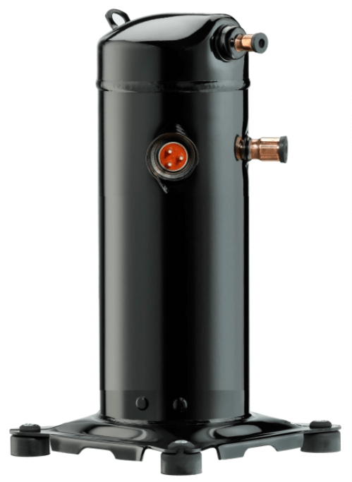
Compressor
2. Condenser: Half the magic happens here as high-pressure vapor pumped from the compressor rejects heat until it has changed state and condensed into a high-pressure sub–cooled liquid.
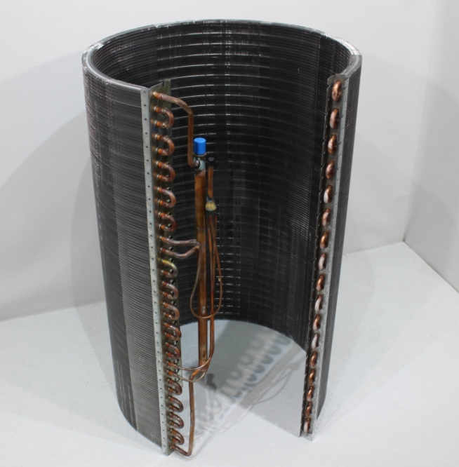
Condenser Coil
3. Metering device: This is where the refrigerant drops from high to low pressure and transforms to a mostly liquid with some vapor (mixed phase) state. Also, it regulates the flow of refrigerant through the evaporator.
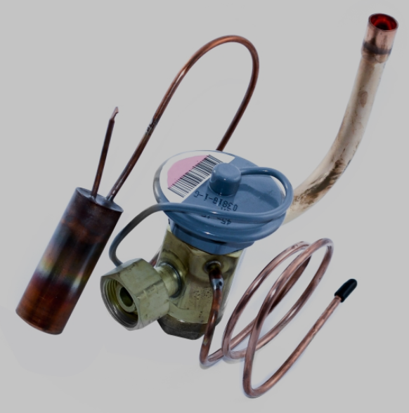
TXV
4. Evaporator: The other half of the magic happens here as low-pressure liquid absorbs heat and changes state to a low-pressure superheated vapor. This vapor then returns to the compressor through the suction line.
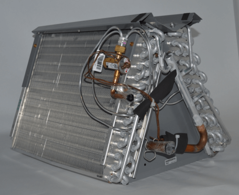
Evaporator Coil
The Refrigeration Cycle in Action
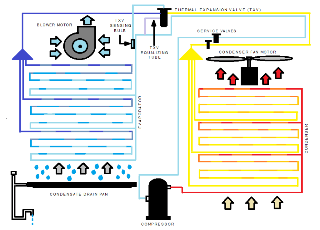
In the graphic, the red refrigerant line represents high-pressure vapor from the compressor. As this discharge vapor flows through the condenser, it rejects heat into the air, gradually changing state to a high-pressure liquid. This change is represented by colors transitioning from red to orange. The refrigerant continues to reject heat, becoming a liquid that is sub–cooled beyond its saturation point, shown in yellow. Then it flows to the metering device (TXV), which provides the drop in temperature and pressure. On the outlet side of the TXV, the refrigerant has transformed to a low-pressure, mostly liquid (mixed phase) state, represented by dark blue. As air is pulled across the coil by the blower, heat is absorbed from the air into the refrigerant causing it to change state from liquid to vapor, represented by the colors transitioning from grey to blue. The pale blue line represents superheated vapor that has absorbed heat beyond its saturation point.
Tips and Tricks: Latent Heat as Humidity
It is important to note that a second process of heat removal occurs in the evaporator when its surface temperature is below dewpoint of the air passing across it. A space with high relative humidity (latent heat) will affect the system’s ability to remove sensible heat from the air. This must be considered when diagnosing an issue or trying to get a refrigerant charge exactly right. As the humidity of a space falls in line, the performance of sensible heat removal will improve.
Why the Magic is in the Change
The HVACR industry almost exclusively uses the BTU (British thermal unit) as its measurement of heat. One BTU is the amount of heat or energy required to raise one pound of water by one degree Fahrenheit. This is a constant while the water remains a liquid between 32F and 212F. To transform this water into one pound of 212F vapor, it requires significantly more energy at 970 BTUs. Most of the work happens during the change of state. This principle is utilized in refrigeration by designing a system that can force the changes of state of a refrigerant from vapor to liquid, and then back to vapor again to move heat where we want it to go.
A Review of Terminology
- Discharge is the high-pressure hot gas (vapor) refrigerant as it leaves the compressor. It maintains the superheat carried over from the suction. If it exceeds 225F, then the compressor oil may breakdown causing an eminent lubrication failure. Most compressors have an internal thermal switch that will open before it reaches critical temperatures.
- Liquid is the sub-cooled refrigerant as it leaves the condenser after it has rejected enough heat to change state from a high-pressure vapor. Also, it is the state of low-pressure refrigerant leaving the metering device before it absorbs enough heat to change to a low-pressure vapor in the evaporator.
- Suction is the low-pressure superheated vapor as it leaves the evaporator and travels to the compressor. A TXV type metering device uses a sensing bulb charged with the same refrigerant as the system to open or close, as needed, to keep an optimal amount of refrigerant moving through the evaporator coil.
- Saturation is the specific temperature of a refrigerant at a specific pressure when in a resting condition. ***Tips and tricks: Knowing the exact temperature of a refrigerant drum (vs a PT chart) is a great way to calibrate the pressure on your gauges.
- Superheat is the heat absorbed into a refrigerant above its saturated vapor point. This measurement tells how the evaporator is performing. High superheat means the liquid has boiled off too soon and the evaporator is starved for refrigerant. Little or no superheat means that the liquid is making it through the coil.
- Sub-cooling is the heat rejected from a liquid refrigerant below its saturation point. This measurement tells how the condenser is performing. High sub-cooling means the refrigerant is backing up in the line from the metering device. Little or none means the high-pressure vapor from the compressor is not changing state properly.
Basic Refrigeration Diagnosis
What Happens if Air is Restricted through the Outdoor Coil?
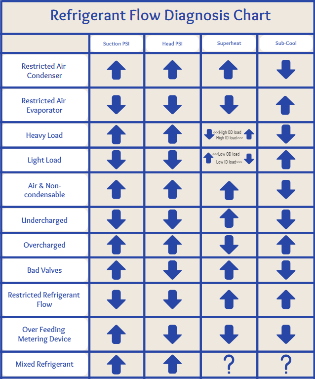
The high-pressure refrigerant is hindered from rejecting heat and changing state to a liquid. Suction, head (liquid) pressure will be elevated. Superheat will be high and there will be little to no sub-cooling.
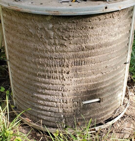
What Happens if Air is Restricted through the Indoor Coil?
The low-pressure liquid refrigerant is hindered from absorbing heat and changing state to a vapor. Suction and head pressures will be low with little to no superheat and elevated sub-cooling.
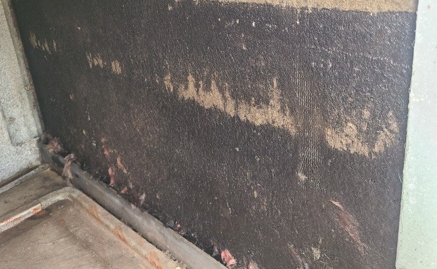
Dirty Evap Coil
How Does a Heavy Ambient Load Affect my Readings?
Suction and head pressures will be elevated. Superheat will vary depending on indoor and outdoor conditions. Sub-cooling will usually be lower than normal.
How Does a Light Ambient Load Affect my Readings?
Suction and head pressure will be diminished. Superheat will vary depending on indoor and outdoor conditions. Sub-cool will usually be higher than normal.
How Can I Tell if I have Non-Condensables in the Refrigerant?
Suction and head pressures and will be elevated. Superheat will usually be high and Sub-cool low.
***Tips and Tricks: The best way to verify if you are dealing with non-condensables is to pump the system down. Once the refrigerant is isolated in the outdoor unit, unwire the compressor and run just the condenser fan for about 10 minutes to acclimate the refrigerant. Then compare your refrigerant pressure against a PT chart. If it is higher than the chart, you have non-condensables.
What Happens when the Refrigerant Charge is Low?
Suction and head pressure will be low because there is not enough refrigerant in the system to complete the changes of state in the condenser and evaporator. Superheat will be high. There will be little to no sub-cooling.
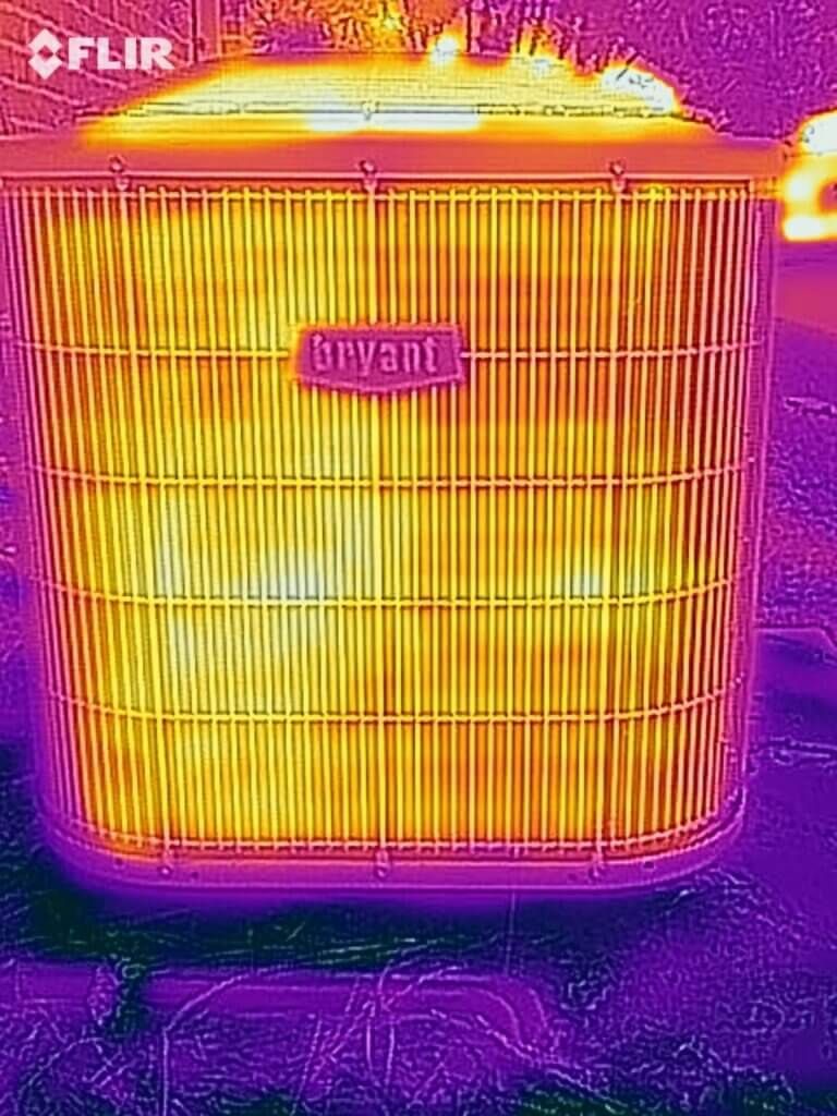
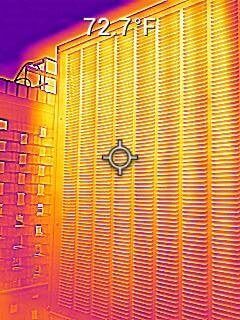
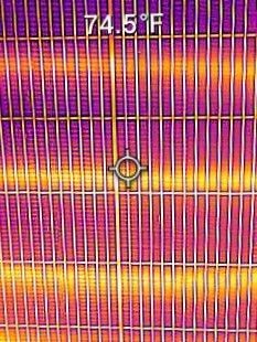
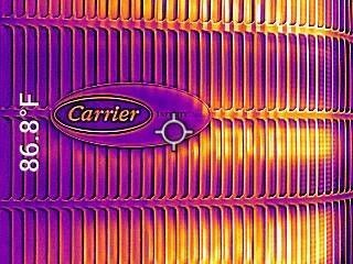
***Tips and Tricks: You can use a thermal camera to see if a condenser is sub-cooling the liquid. In the following photos, the two units on the top have little to no sub-cooling while the two on the bottom have proper sub-cooling, as shown by the banding of color.
What Happens when the System is Over-Charged?
Suction and head pressure will be elevated. There will be little to no superheat. Sub-cooling will be high as the refrigerant molecules stack up on the inlet side of the metering device.
How Can I Tell I have Bad Valves in the Compressor?
Suction pressure will be elevated, and head pressure will be diminished. Superheat will be high. There will be little to no sub-cooling. ***Tips and tricks: Try to pump the system down. If the system will not pump down or stabilizes at a positive pressure, without trying to bypass refrigerant, it is likely the valves will have failed.
What Happens when the Metering Device gets Restricted?
Suction pressure will usually be lower than normal. Head pressure may be elevated. Superheat will be high. Sub-cooling will be high as refrigerant molecules stack up on the inlet side of the metering device.
What Happens when the System is Over-Metering?
Suction pressure will be high and head pressure will be low. There will be little to no superheat and sub-cooling. The causes for this depend on the type of metering device.
How Can I Tell if I Have Mixed Refrigerant?
Suction and head pressures are usually elevated. Depending on the mix of refrigerant, superheat and sub-cool are completely variable.
***Tips and Tricks: This diagnosis can apply to some blended refrigerants that become fractured.
An old, printed copy of the chart below helped me immensely at the beginning of my service career. I hope it can help you the way that it helped me….
Disclaimer: The technical statements, information and recommendations contained herein are believed to be accurate as of the date hereof, but Mingledorff’s does not make representations or warranties, express or implied, as to its accuracy, its completeness, or the results to be obtained. The information is being provided for informational purposes only and is intended for use by persons having adequate skill and expertise regarding the proper selection, use and application of the products and recommendations and at their own risk and discretion.
Unlock the Full Potential
This installation was on a 4-story home, and the tech had not yet gone to the basement to troubleshoot the “infinity” water source heat pump, as he was told he by the homeowner. He was in the attic at the infinity furnace above the 4th floor. He was getting his dcv in the proper range on his A and B green plug on the air handler, 3 to 4 vdc. His indoor board ohm reading was in range, 28k to 32 k. The tech ohmed out the A and B thermostat wires on the water source heat pump from the upstairs. His ohm reading was not in range of a normal infinity board. His reading was around 64.4k. The tech then made the long walk to the basement where the “geothermal heat pump” was located. Bingo.
More to Explore

Heat Pump
Keep up with the latest HVAC news from Mingledorff’s Inc.