

Unlock the Full Potential
This installation was on a 4-story home, and the tech had not yet gone to the basement to troubleshoot the “infinity” water source heat pump, as he was told he by the homeowner. He was in the attic at the infinity furnace above the 4th floor. He was getting his dcv in the proper range on his A and B green plug on the air handler, 3 to 4 vdc. His indoor board ohm reading was in range, 28k to 32 k. The tech ohmed out the A and B thermostat wires on the water source heat pump from the upstairs. His ohm reading was not in range of a normal infinity board. His reading was around 64.4k. The tech then made the long walk to the basement where the “geothermal heat pump” was located. Bingo.

July 10, 2023
The Dreaded P4 Code
Have you ever shown up to a service call on a Carrier/Bryant/WeatherMaker (Midea) ductless system and found it locked out on a P4 or PC04 error code showing on the indoor display? Did the code return after a power cycle? Did the unit attempt to run? This article will help you understand what these codes mean and how to troubleshoot them effectively.
When working on any system, it is important to know the model number. These codes can mean different problems depending on the equipment, and where the error is displayed. In this article, I am referring to the following outdoor models:
- (P4) 38MAQ, 38MBR, 38MHR, 38MPRA
- (PC04) 38MAR, 38MPRB
Tips and Tricks: The following diagnostics can also apply to P6 and PC00 codes for IPM Protection
What do these codes mean? P4 and PC04 are Inverter Compressor Drive errors. Even though they sound specific, these codes can be generated from a broad spectrum of component failures and operating issues within the system.
Know your Voltage
Read L1 to L2. What is the actual line voltage vs the minimum and maximum listed on the data plate? Read each leg to ground. Are they balanced? Check the main breaker, next the disconnect, and then the equipment. Was there any drop or difference in the voltage?
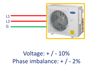
Replacing a part may remedy a symptom, but not necessarily the cause. Dirty power issues can be overlooked when components have failed. If left unchecked, voltage that is too high, too low, or imbalanced can make for recurring issues.
Understand the Inverter Components and Their Purpose
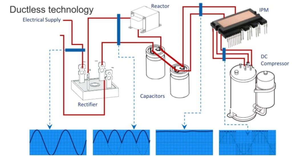
The graphic above shows the components and the change in the sine wave through the inverter circuit
The first stop in the inverter power circuit is the bridge rectifier. Its purpose is to convert the AC line voltage to DC. In essence, it flips the bottom half of the sine wave to the top. The formula for DC output is 1.414 x AC line voltage. Next in the circuit are the reactor and capacitors. These components pull tension on and flatten out the sine wave. Then the IPM (Intelligent Power Module) or IGBT (Insulated Gate Bipolar Transistor) uses this voltage to send precisely controlled frequency to the compressor and DC fan motor(s).
After you have verified a good power supply to the equipment, perform a visual inspection of the wiring and circuitry. Some issues are more obvious than others.
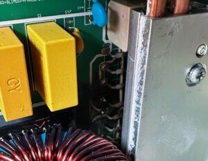
Lightning prevails over circuitry
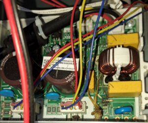
Tree frog had a bad day
Check the Reactors and Capacitors
These components are integral to the inverter circuit. Capacitors can usually be found bad on a visual inspection. Failures in reactors are uncommon, and they can be easily overlooked. Reactors should ohm very close to zero resistance. They should never be open or have any continuity to ground.
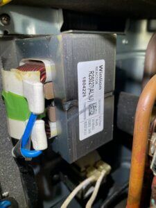
Example of a reactor

Check the Compressor

Above: Toasted Compressor Blanket
Has the sound blanket turned from green to brown? This is a sure sign it has overheated or possibly become demagnetized. Ohm the compressor windings. Remember, this is a three-phase motor. Your measurements should be balanced and less than 2.25 ohms. Nothing should read open or continuity to ground.

Ohm Values for the Windings of Select Model Compressors
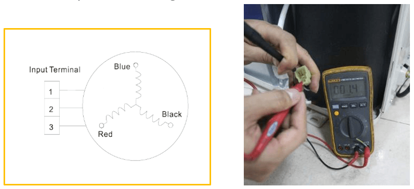
Ohm the Windings from the Wire Harness Connector
Check the DC Fan Motor(s)
Does it spin freely? If not, then the bearings have failed. If yes, then ohm the windings from the UVW connector. It will be a much higher resistance than the compressor but should still be balanced between any two pins. It should not be open or grounded. On units with two motors, perform the process with each.
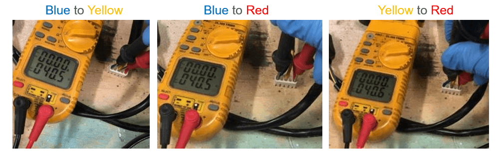
If the fan motor windings read correctly, further investigation may be necessary. Turn on power to the unit. Some motors use feedback for speed recognition. During standby, 5 VDC should always be present on the 4 & 5 pins of the feedback connector.
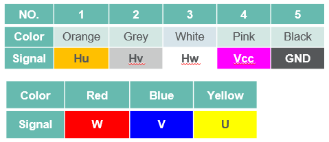
DC fan motor wire color and designation chart
If it is not present, you have a shorted PC board. If it is present, then progress to the next step. Rotate the fan by hand and measure pins 1 & 5, 2 & 5, and 3 & 5. If any negative voltage is displayed, then replace the motor.
Check the Inverter (IPM)
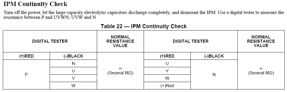
If your meter cannot read Meg Ohms, it will display OL
Learning to find all these check points on the back of a control board takes time and experience. Every board is different. If they do not have to be returned for warranty purposes, save your failed parts for practice and study tools.
Communication is Key
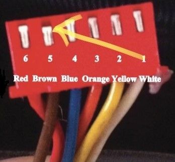
Example of a misaligned connector
Bad communication between the main PC and the Inverter can cause a P4 code. Check the wired connectors for poor alignment. This can happen when components are replaced, and someone pulled on the wires instead of the connector. Loose connections can wreak havoc on a communication circuit.
Review of Possible Causes for P4 and PC04 Codes
- High, Low, or Imbalance Voltage
- Shorted PC and/or IPM Boards
- Problems with the Compressor
- Problems with the DC Condenser Fan Motor(s)
- Faulty Communication between Main PC and IPM
- Miswiring and Loose Connectors
- Liquid in the Refrigerant (remote possibility)
Hopefully, the knowledge from this article will take some of the dread out of diagnosing a unit with these error codes and help you be more efficient when working with ductless products.
Disclaimer: The technical statements, information and recommendations contained herein are believed to be accurate as of the date hereof, but Mingledorff’s does not make representations or warranties, express or implied, as to its accuracy, its completeness, or the results to be obtained. The information is being provided for informational purposes only and is intended for use by persons having adequate skill and expertise regarding the proper selection, use and application of the products and recommendations and at their own risk and discretion.
Unlock the Full Potential
This installation was on a 4-story home, and the tech had not yet gone to the basement to troubleshoot the “infinity” water source heat pump, as he was told he by the homeowner. He was in the attic at the infinity furnace above the 4th floor. He was getting his dcv in the proper range on his A and B green plug on the air handler, 3 to 4 vdc. His indoor board ohm reading was in range, 28k to 32 k. The tech ohmed out the A and B thermostat wires on the water source heat pump from the upstairs. His ohm reading was not in range of a normal infinity board. His reading was around 64.4k. The tech then made the long walk to the basement where the “geothermal heat pump” was located. Bingo.
More to Explore

Heat Pump
Keep up with the latest HVAC news from Mingledorff’s Inc.