
Technical Services logo with red banner and blue swoosh accents
249 VAN Launch Kit 249 VAN Consumer Brochure Smart Thermostat Sell Sheet 249 VAN Launch Kit

Unlock the Full Potential

View Quick Start Guide

This installation was on a 4-story home, and the tech had not yet gone to the basement to troubleshoot the “infinity” water source heat pump, as he was told he by the homeowner. He was in the attic at the infinity furnace above the 4th floor. He was getting his dcv in the proper range on his A and B green plug on the air handler, 3 to 4 vdc. His indoor board ohm reading was in range, 28k to 32 k. The tech ohmed out the A and B thermostat wires on the water source heat pump from the upstairs. His ohm reading was not in range of a normal infinity board. His reading was around 64.4k. The tech then made the long walk to the basement where the “geothermal heat pump” was located. Bingo. 

Now get out there and organize some zone wiring!

Zone equipment would be identified as indoor unit- blue black/ outdoor unit-blue green:
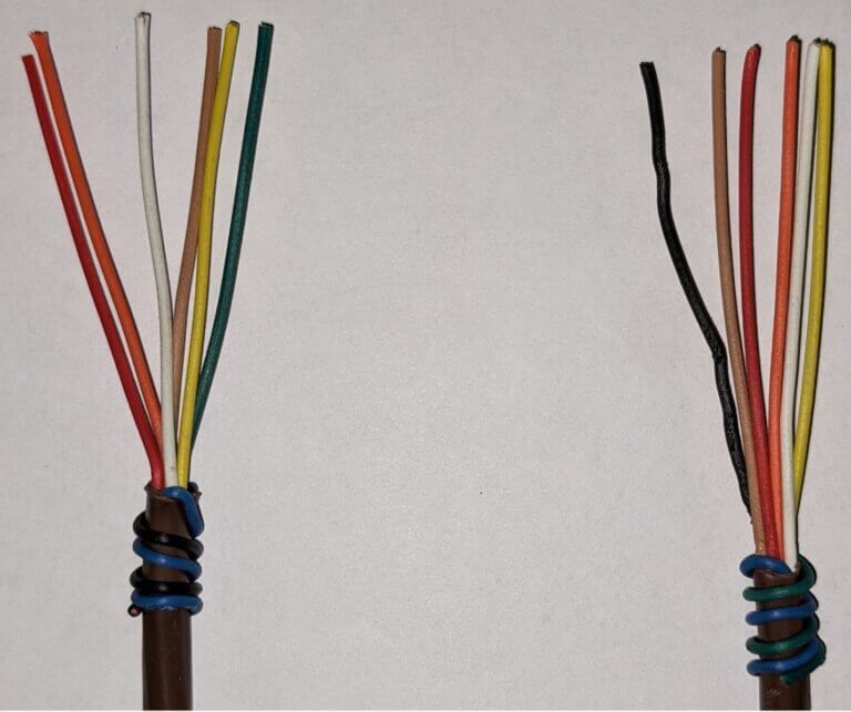
Two wire bundles with colored insulated strands and blue tape ties on brown cable ends.
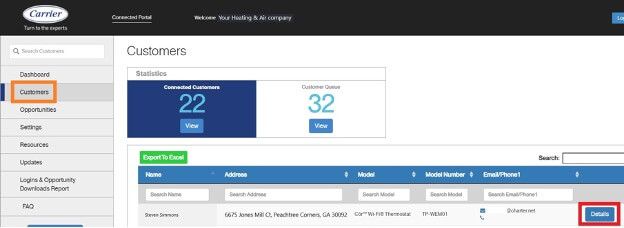
CRM dashboard showing customer list, summary cards, and a highlighted button on the right

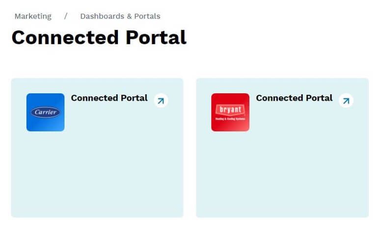
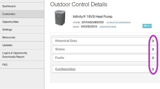
I have cropped some screens, and modified the serial numbers to keep certain dealer and customer’s information private. Setting the customers up on the portal is an easy process and could reap many benefits. Carrier and Bryant are going to begin utilizing this portal more with new upcoming equipment.


Get out there and get connected to the portal!
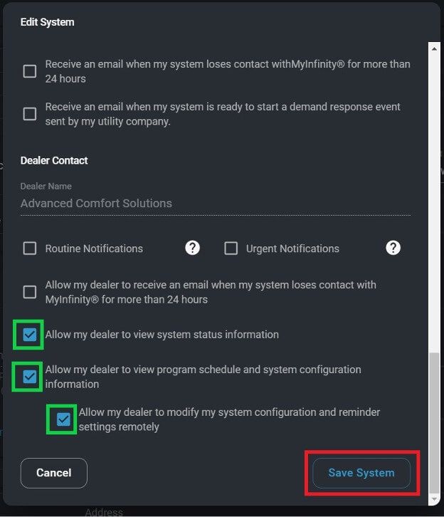
Dark “Edit System” settings dialog with multiple checkboxes and a blue Save System button
Marketing dashboard showing two “Connected Portal” cards with blue and red app icons.
Outdoor Control Details page with sidebar menu and expandable sections, highlighted by purple arrows on the right

*Wiring diagrams highlighted with colors chosen for high contrast- not for wire color designation*

Low voltage starts in the red box at the transformer, 24vac goes to the Indoor Fan Board (IFB), through a fuse and on to the thermostat. Depending on what the thermostat calls for, 24vac will be sent down a different wire(s) to turn on/off the multiple devices in the system. The other low voltage wire (C) has an unbroken path to EVERY component in the unit. I have highlighted the pathway in blue and circled each component in purple. This wire/path is something each device has in “common”—it is the common wire. In layman’s terms, the common wire is the return pathway for voltage to come back to the transformer since it left out on the 24vac side.


The Common wire/terminal is always the one thing that is relatable or in common with the surrounding wires/terminals. Relays, motors, control boards, and even transformers all have some type of common wire/terminal. Common for a relay isn’t the same as common on a motor, but within each given device they carry the same meaning. Now go back and reread the second paragraph above—it will have a deeper meaning now.


Challenge: Check out the high voltage side of the Transformer. It has a COM terminal…. it’s not low voltage common. What is it?


That’s all.

Loading PDF…

Picture of Steven Simmons

Steven Simmons

Technical Services Manager Southwest District

December 30, 2021

Scrolling Marquee Basics and Resetting Error Codes

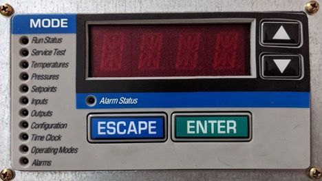
On units that are equipped with a ComfortLink controls package, the user interface for the machine will include a Scrolling Marquee keypad as shown below.

Close-up of a machine control panel with red display, mode list, and ESCAPE and ENTER buttons

This ComfortLink controls package can be factory installed on nearly all light commercial and applied product lines. Including but not limited to 30RB & 30RAP chillers, 48/50HC RTUs, and 48/50A & 48/50N & 48/50P series RTUs.


Using the buttons:


On the left side of the Marquee under MODE there are 11 categories.


The UP/ DOWN buttons can be used to navigate between them and also be used to navigate between the many different sub modes.


The ENTER button will advance into the mode category that is highlighted by a red light.


The ESCAPE button will bring you back out of that mode.


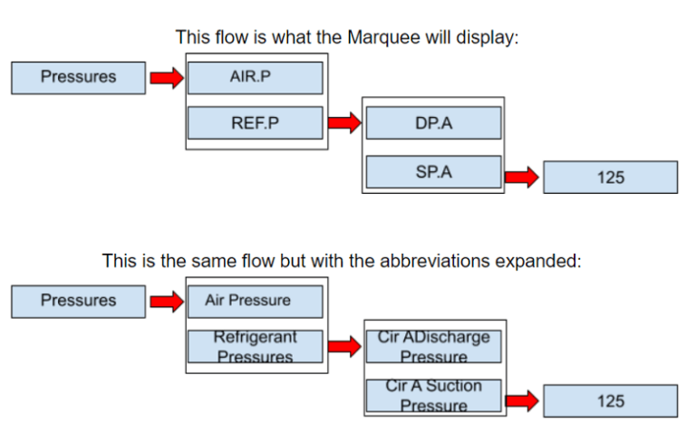
Each mode category (there are 11) has its own set of sub modes that flow in a left-to-right manner. Using the instructions above, you can use the ENTER and ESCAPE buttons to go into or come out of sub modes.


Here are two examples:

Diagram showing pressures flowing through a Marquee and abbreviated labels expanding to full terms.

Expanding the display abbreviations:


When navigating through the modes and sub modes, most of the actual names will be abbreviated. At any time when the display is showing an abbreviation, you can press the ENTER and the ESCAPE buttons at the same time to expand what it means. When this button combination is done the marquee will scroll the wording that the abbreviation stands for. If pressing them at the same time is difficult, you can press the ENTER button and hold it then press the ESCAPE button. While the marquee is scrolling the words, you can press the ENTER button again to pause or play the scrolling message.


Checking out errors


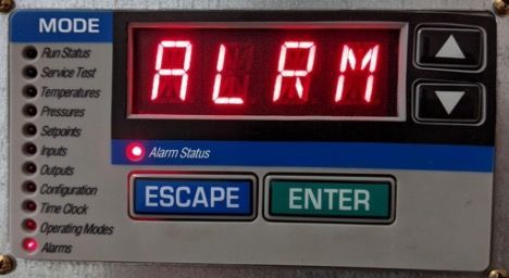
If the red LED is lit up solid next to Alarm Status, this is an indication that something within the unit itself or something outside of the unit has caused the system to shut down to further protect itself from damage. To get the system to come back online, the problem must be identified, corrected, and then the error code needs to be reset.

Close-up of a control panel showing red “ALRM” display with Escape and Enter buttons

When it comes to checking and resetting an alarm(s), all the machines have the same instructions but the actual abbreviations may vary. Here is the flow without abbreviations:

Flowchart for ALARMS menu with red arrows to Reset All, Alarm History, and Current Active options.

While viewing the alarms in Alarm History or Current Active Alarms you can press the ENTER and ESCAPE buttons at the same time as mentioned above and the marquee will scroll the description of what the error means along with the time and date that it occurred. The same rules apply for pausing/ playing the message as well. When looking at this data it is important to also know what the system’s time and date are to ensure you get a valid timeline for the errors.


When you enter the list of alarms either current or active you can use the up/down buttons to see what the other alarms are if they exist.


7NO” will begin to flash.


Use the Up/Down buttons to change No to Yes and press enter.


The screen will display “Yes” briefly and will reset itself back to “No”.


The LED next to Alarm Status will turn off.


If the LED is still illuminated, then the problem wasn’t corrected or another issue has come up.


***If you are prompted for a password: for the purposes of this letter I will not disclose what to enter but I will advise that the password can be found in the Controls, Troubleshooting, Operation manual for your system.


The operator of the marquee should assume all responsibility in ensuring that the reasons that caused the system’s alarms are corrected prior to resetting the alarms.***

249 VAN Launch Kit 249 VAN Consumer Brochure Smart Thermostat Sell Sheet 249 VAN Launch Kit

Unlock the Full Potential

View Quick Start Guide

This installation was on a 4-story home, and the tech had not yet gone to the basement to troubleshoot the “infinity” water source heat pump, as he was told he by the homeowner. He was in the attic at the infinity furnace above the 4th floor. He was getting his dcv in the proper range on his A and B green plug on the air handler, 3 to 4 vdc. His indoor board ohm reading was in range, 28k to 32 k. The tech ohmed out the A and B thermostat wires on the water source heat pump from the upstairs. His ohm reading was not in range of a normal infinity board. His reading was around 64.4k. The tech then made the long walk to the basement where the “geothermal heat pump” was located. Bingo. 


More to Explore

Family relaxing in a bright living room, parents on a gray couch with laptops while children play nearby
By Austin Sims August 4, 2026
At Mingledorff's we understand your business. We are your #1 HVAC and plumbing distributor choice. Trust our experience. Contact us today!
Mingledorffs
By Jenny Reed August 4, 2026
At Mingledorff's we understand your business. We are your #1 HVAC and plumbing distributor. Trust our experience. Contact us today!
Bright hobby shop with display cases, counter, and model kits; a few people stand near the back.
By Jenny Reed August 3, 2026
At Mingledorff's we understand your business. We are your #1 HVAC and plumbing distributor. Trust our experience. Contact us today!
Bright hobby shop interior with display cases, model kits, and a counter with two people inside.
By Jenny Reed August 3, 2026
At Mingledorff's we understand your business. We are your #1 HVAC and plumbing distributor. Trust our experience. Contact us today!

Heat Pump

Keep up with the latest HVAC news from Mingledorff’s Inc.