
Technical Services logo with red banner and blue swoosh accents
249 VAN Launch Kit 249 VAN Consumer Brochure Smart Thermostat Sell Sheet 249 VAN Launch Kit

Unlock the Full Potential

View Quick Start Guide

This installation was on a 4-story home, and the tech had not yet gone to the basement to troubleshoot the “infinity” water source heat pump, as he was told he by the homeowner. He was in the attic at the infinity furnace above the 4th floor. He was getting his dcv in the proper range on his A and B green plug on the air handler, 3 to 4 vdc. His indoor board ohm reading was in range, 28k to 32 k. The tech ohmed out the A and B thermostat wires on the water source heat pump from the upstairs. His ohm reading was not in range of a normal infinity board. His reading was around 64.4k. The tech then made the long walk to the basement where the “geothermal heat pump” was located. Bingo. 

Now get out there and organize some zone wiring!

Zone equipment would be identified as indoor unit- blue black/ outdoor unit-blue green:
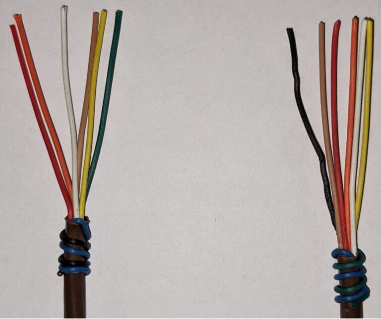
Two cable ends with exposed multicolored wires, showing different wire arrangements on a white background
Picture of Anthony Coker

Anthony Coker

Technical Services Manager North Georgia District

June 2, 2022

Condensate Pump Replacement

We are finding ourselves with more and more VRF components that will require maintenance periodically. Example: a 40VMF


Below are the procedures of handling one of the components mentioned above. As always, please take your time and use precautions in all work you perform.


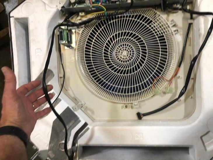
12 Steps to replace a Condensate Pump on a 40VMF


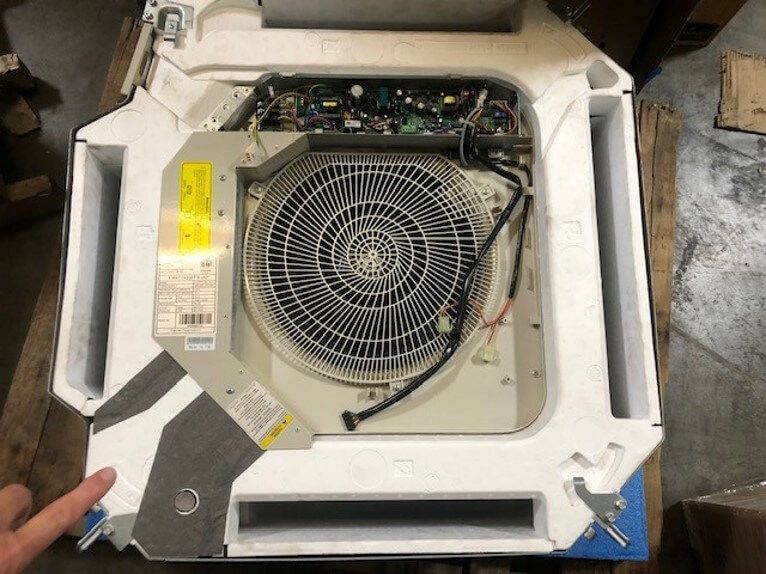
1) This is the location of the condensate pump in relation to the control compartment

Top view of an open industrial machine with a large circular fan and exposed wiring inside a white housing

Step 1

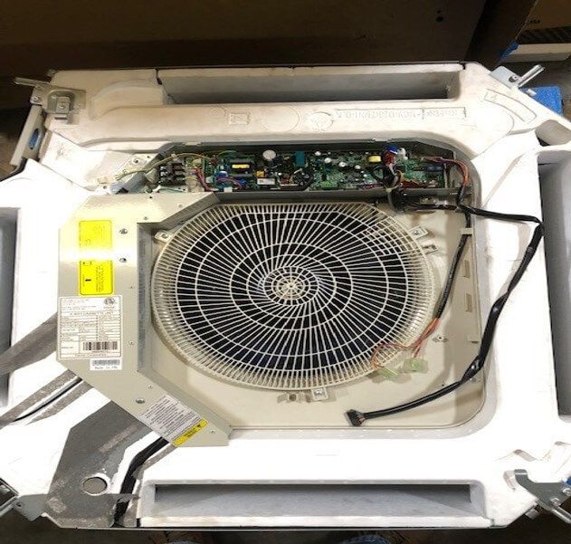
2) Remove all screws from the four corners indicated by the arrows

Open appliance with exposed fan and circuit board inside a white casing

Step 2

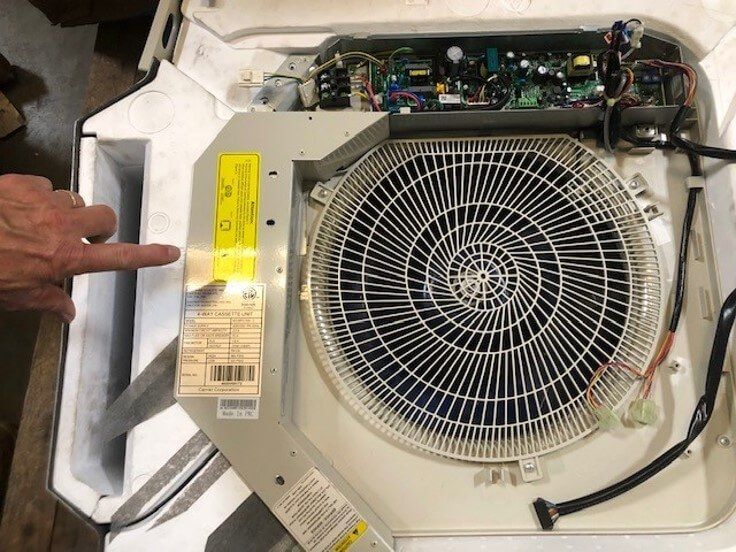
3) Remove the 3 screws to remove wire routing cover. 

Open appliance with large fan assembly and circuit board, a hand pointing at a label.

Step 3

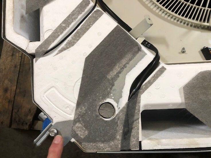
4) Remove the felt tape covering the wire route

Close-up of a metal mechanical part with a bolt and circular opening on a workbench.

Step 4

5) Trace the pump high voltage wiring harness to the control compartment 

Hand beside a circular fan assembly inside a white appliance compartment with exposed wiring.

Step 5

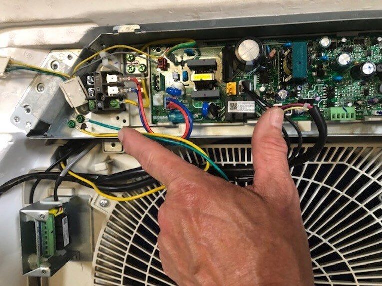
6) Unplug the 2 black wire connectors from the pump connector on the control board and unscrew the green ground wire from the control compartment 

Hand pointing to wiring and circuit board inside an HVAC unit near a fan

Step 6

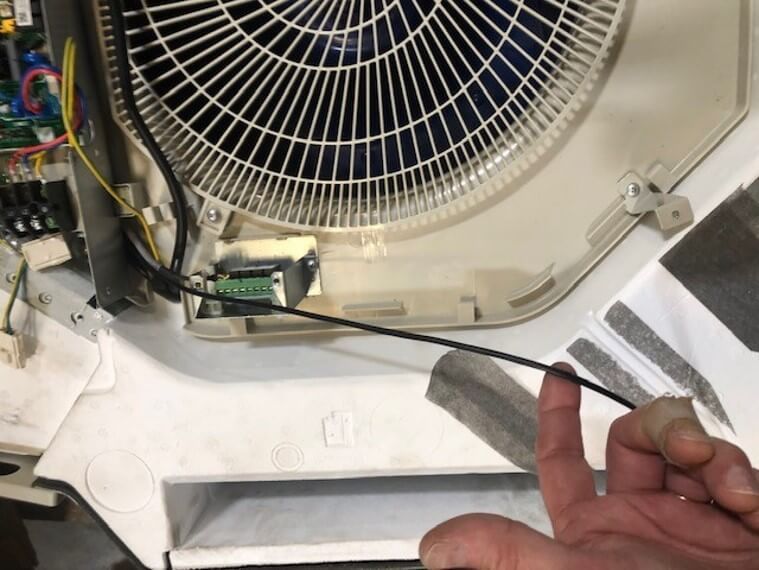
7) Trace out the pump float alarm cable. Notice that it runs under the control compartment and will require taking the control compartment screws out. Let it hang down so you can access the wire all the way over to the wire bundle on the right side of the control compartment.

Inside an appliance, a hand points to wiring and a small circuit board near a fan

Step 7

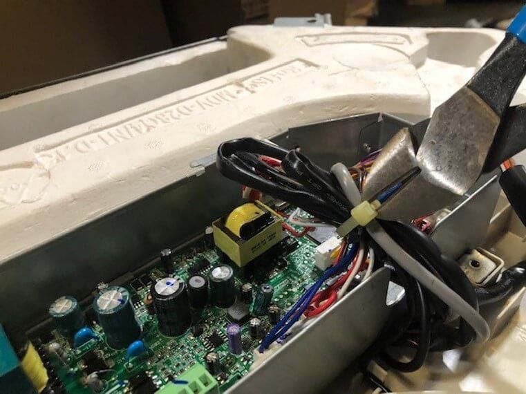
8) To remove the control compartment first cut the wire tie holding the wire bundle together. 

Electronics board with capacitors and wires, clamped by pliers inside a white plastic case

Step 8

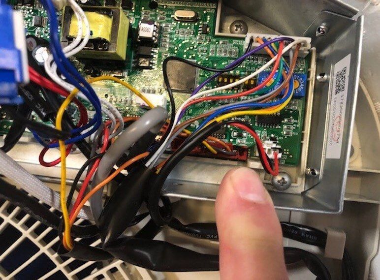
9) Next unplug the red and black 2 wire plug from the water connector on the control board 

Close-up of a device’s circuit board with multicolored wires and a finger pointing at a connector

Step 9

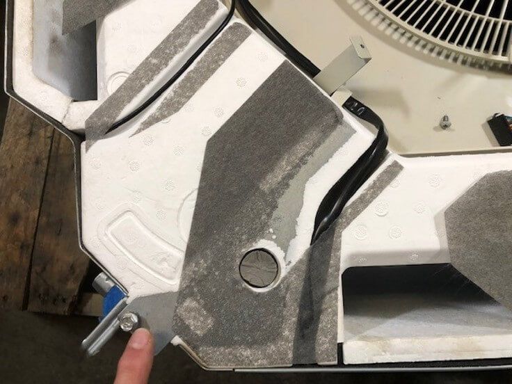
10) Once you have both cables disconnected remove them from the wire route in the bottom of the foam drain pan.

Close-up of a gray and white mechanical device with a bolt and textured surface on a wooden floor.

Step 10

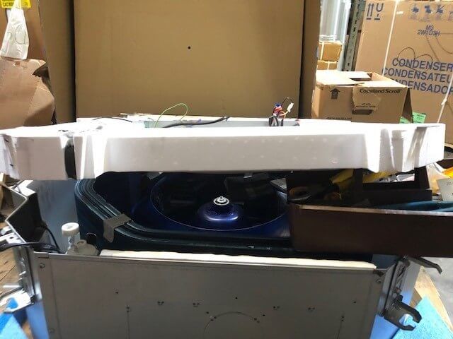
11) Next you pull the drain pan down about 2 to 3 inches all the way around the unit. You will then be able to pull the condensate pump side down about 10 inches. 

Damaged white appliance with a blue circular component inside a cluttered storage area

Step 11

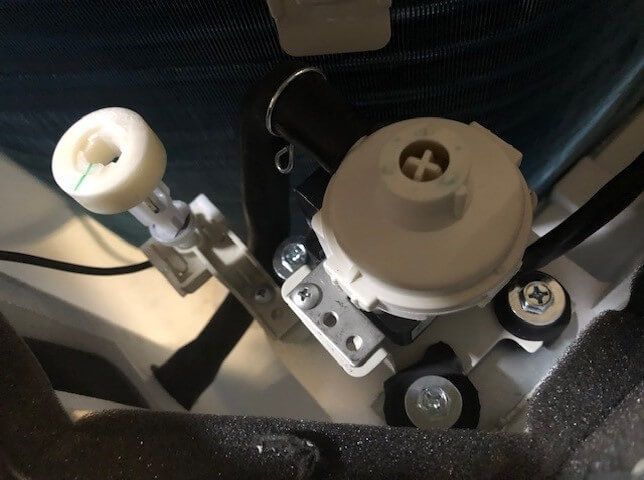
12) You will then be able to access the pump Assembly which can now be removed by removing the 3 mounting screws.

Close-up of a car seat mechanism with a gray adjustment knob and metal bracket

Step 12

To complete the replacement, install the new condensate pump assembly and reverse the previous steps. 

249 VAN Launch Kit 249 VAN Consumer Brochure Smart Thermostat Sell Sheet 249 VAN Launch Kit

Unlock the Full Potential

View Quick Start Guide

This installation was on a 4-story home, and the tech had not yet gone to the basement to troubleshoot the “infinity” water source heat pump, as he was told he by the homeowner. He was in the attic at the infinity furnace above the 4th floor. He was getting his dcv in the proper range on his A and B green plug on the air handler, 3 to 4 vdc. His indoor board ohm reading was in range, 28k to 32 k. The tech ohmed out the A and B thermostat wires on the water source heat pump from the upstairs. His ohm reading was not in range of a normal infinity board. His reading was around 64.4k. The tech then made the long walk to the basement where the “geothermal heat pump” was located. Bingo. 


More to Explore

Family relaxing in a bright living room, parents on a gray couch with laptops while children play nearby
By Austin Sims August 4, 2026
At Mingledorff's we understand your business. We are your #1 HVAC and plumbing distributor choice. Trust our experience. Contact us today!
Mingledorffs
By Jenny Reed August 4, 2026
At Mingledorff's we understand your business. We are your #1 HVAC and plumbing distributor. Trust our experience. Contact us today!
Bright hobby shop with display cases, counter, and model kits; a few people stand near the back.
By Jenny Reed August 3, 2026
At Mingledorff's we understand your business. We are your #1 HVAC and plumbing distributor. Trust our experience. Contact us today!
Bright hobby shop interior with display cases, model kits, and a counter with two people inside.
By Jenny Reed August 3, 2026
At Mingledorff's we understand your business. We are your #1 HVAC and plumbing distributor. Trust our experience. Contact us today!

Heat Pump

Keep up with the latest HVAC news from Mingledorff’s Inc.