

Unlock the Full Potential
This installation was on a 4-story home, and the tech had not yet gone to the basement to troubleshoot the “infinity” water source heat pump, as he was told he by the homeowner. He was in the attic at the infinity furnace above the 4th floor. He was getting his dcv in the proper range on his A and B green plug on the air handler, 3 to 4 vdc. His indoor board ohm reading was in range, 28k to 32 k. The tech ohmed out the A and B thermostat wires on the water source heat pump from the upstairs. His ohm reading was not in range of a normal infinity board. His reading was around 64.4k. The tech then made the long walk to the basement where the “geothermal heat pump” was located. Bingo.
If no equipment is found, you may need to resync your device.
If any of the details seem suspect, then further investigation is necessary. As these units can change how they operate based on inputs, the information being correct is critical. Use your gauges and meter to compare and contrast versus the data. Compressor RPMs are converted from hertz. The minimum and maximum RPMs varies by ton. This information can be found in the product data under “Sound Power Level (dBA)”. The suction temp, outdoor coil temp, and outdoor ambient temp inputs are all 10K ohm thermistors. The discharge temp is a 50K ohm thermistor. These ohm value charts for both types are readily available online. Pressure transducers take a 5 VDC output from the main PC board and provide a signal return between .5 to 4.5 VDC back to the board. This value is put through a formula to provide a pressure reading between 0 and 620.
If any of the details seem suspect, then further investigation is necessary. As these units can change how they operate based on inputs, the information being correct is critical. Use your gauges and meter to compare and contrast versus the data. Compressor RPMs are converted from hertz. The minimum and maximum RPMs varies by ton. This information can be found in the product data under “Sound Power Level (dBA)”. The suction temp, outdoor coil temp, and outdoor ambient temp inputs are all 10K ohm thermistors. The discharge temp is a 50K ohm thermistor. These ohm value charts for both types are readily available online. Pressure transducers take a 5 VDC output from the main PC board and provide a signal return between .5 to 4.5 VDC back to the board. This value is put through a formula to provide a pressure reading between 0 and 620.
Tip: By the math, the formula is trasnducer signal VDC (x) minus .5 times 155. Or 155(x-.5)= pressure. Examples: High 155(4.5-.5)= 620 PSI, low 155(.5-.5)= 0 PSI, mid-range 155(2.3-.5)= 279 PSI and 155(1.3-.5)= 124 PSI.
Validating the position of the EXV(s) is not possible. If it comes into question, you can verify the integrity of the stepper motor by ohming out each of its multiple coil circuits. You can also verify the 12VDC from the PC when commanding a position change. If both of these check out, then the internal valve is stuck or restricted.
The PFCM and IPM temperatures are built into the inverter which is not serviceable.

Roger Siling
Technical Services Trainer
March 31, 2020
Carrier/Copeland Internal Compressor T.O.D. (Therm O Disc™) Safety Device
The internal discharge temperature protection device resides inside the Carrier compressor scroll area, between the high pressure and low pressure scroll area, or on the muffler plate.
During a situation such as loss of charge, the Carrier compressor will be protected for some time after it trips the motor protector.
First, the T.O.D. is designed to open and route the excessively hot discharge gas down towards the motor protector, when the internal discharge gas temperature exceeds 290°F.
- Used on 3-phase compressors
- Helps prevent compressor overheating due to low refrigerant charge
- Trip temperature is 290°F
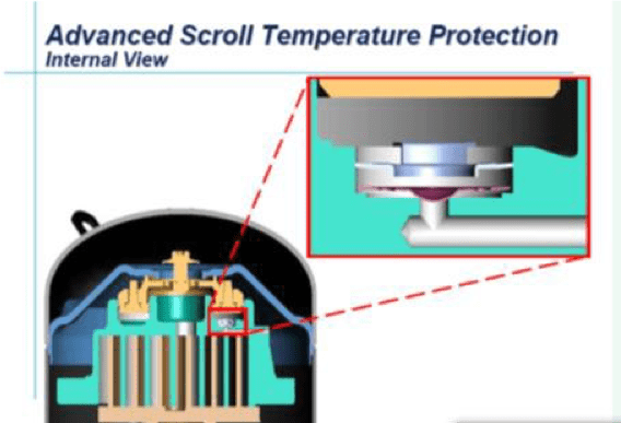
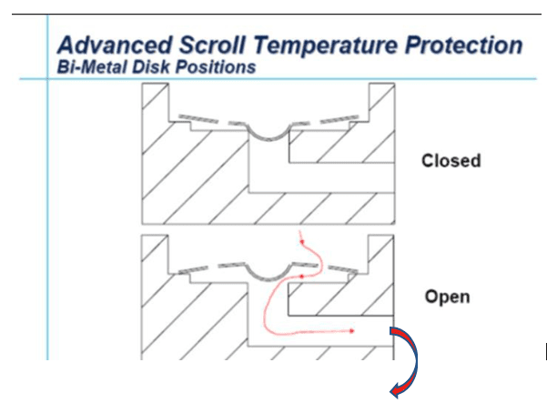
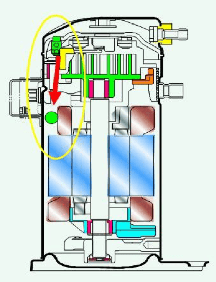
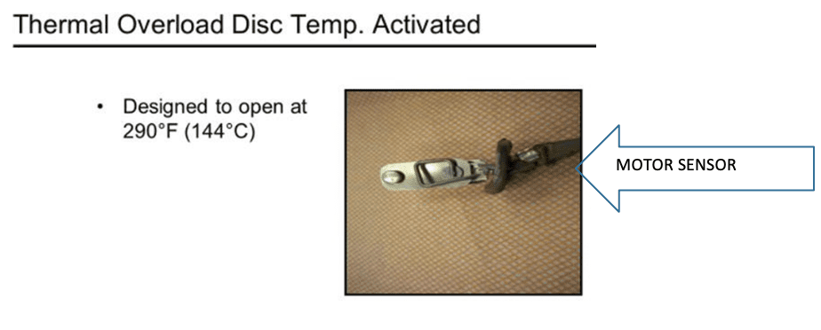
As the motor thermal overload disc reaches its 290°F set-point temperature, it opens the circuit and stops the compressor operation. After some time has elapsed, the compressor motor winding thermal overload cools down and resets, causing the compressor to restart. Since this Carrier compressor motor overheating issue is usually caused by a system running low on charge it is imperative that the leak source be found and repaired before compressor damage can occur. If continued compressor overheated operation is allowed to continue, compressor damage, or destruction can occur. Compressor damage, or destruction can cause debris and acid formation in the system and must be cleaned up and removed from the system, to prevent further damage to the new compressor.
An additional compressor protector such as a manual reset low pressure switch should be added to the system as an additional fail safe mechanism.
Learn more about Copeland Scroll™ compressors by watching the video below.
Unlock the Full Potential
This installation was on a 4-story home, and the tech had not yet gone to the basement to troubleshoot the “infinity” water source heat pump, as he was told he by the homeowner. He was in the attic at the infinity furnace above the 4th floor. He was getting his dcv in the proper range on his A and B green plug on the air handler, 3 to 4 vdc. His indoor board ohm reading was in range, 28k to 32 k. The tech ohmed out the A and B thermostat wires on the water source heat pump from the upstairs. His ohm reading was not in range of a normal infinity board. His reading was around 64.4k. The tech then made the long walk to the basement where the “geothermal heat pump” was located. Bingo.
More to Explore

Heat Pump
Keep up with the latest HVAC news from Mingledorff’s Inc.